5 Structure and function
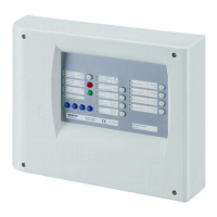
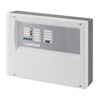
This chapter provides an introduction to the structure of the control unit XC1003-A,
describes the connections and provides an overview of the functions of the optical
indicators (LED), the adjusting elements and keys. Here you will also find the
description of the accessories and the technical data.
PU1
DL1
DL2
2A
2A
CN7
CN8
F2
F1
PU1
CN6
CN5
SW2
SW1
4 3 2 1
KEY
PU10
PU9
PU 6
LED34
LED26LED11
LED12
LED13
LED14
LED15
LED16
LED17
LED18
LED19
LED20
LED21
LED22
LED23
LED24
LED25
LED27
LED28
LED29
LED30
LED31
LED32
LED33
KEY 2
LED10
LED7
LED1
LED2
LED3
LED5
LED6
LED8
LED9
LED4
LD1
LD2
LD3
LD4
LD5
LD6
LD7
LD8
LD9
PU 5 PU 4 PU 3 PU 2
KEY 8KEY 9KEY 10KEY 11KEY 12
CN 1
KEY 5
+ BAT + 24V
KEY 4 KEY 6 KEY 7
PU1
LEVEL 3
PU8
B.S TEST FAB
PU7
KEY 1
KEY13
KEY14KEY15
KEY16
Pre-discharge-warning
time
………………. seconds
11
4
4
1
PU1
DL1
DL2
2A
2A
CN7
CN8
F2
F1
PU1
CN6
CN5
SW2
SW1
4 3 2 1
KEY
PU10
PU9
PU 6
LED34
LED26LED11
LED12
LED13
LED14
LED15
LED16
LED17
LED18
LED19
LED20
LED21
LED22
LED23
LED24
LED25
LED27
LED28
LED29
LED30
LED31
LED32
LED33
KEY 2
LED10
LED7
LED1
LED2
LED3
LED5
LED6
LED8
LED9
LED4
LD1
LD2
LD3
LD4
LD5
LD6
LD7
LD8
LD9
PU 5 PU 4 PU 3 PU 2
KEY 8KEY 9KEY 10KEY 11KEY 12
CN 1
KEY 5
+ BAT + 24V
KEY 4 KEY 6 KEY 7
PU1
LEVEL 3
PU8
B.S TEST FAB
PU7
KEY 1
KEY13
KEY14KEY15
KEY16
Pre-discharge-warning
time
………………. seconds
12
3
2
6
10
100Ω 3W
5
8
9
PU3 PU1 PU2
DL1
RT FAULT RT ALARM
OUPUT RT
PU4 PU3 PU1 PU2
DL1
RT FAULT RT ALARM
OUPUT RT
PU4
7
Fig. 5 Rack XC1003-A with electronics components

 Loading...


