5.4 Indicator elements
The indicator elements (LEDs) are on the XCM1001-2 main board. LEDs 1 to 34
for operating states are visible on the front of the housing. Service LEDs (LD1 to
LD9) provide fault information and are not visible from the outside.
Alternative configuration
Programming step 10/ option 2
Standard configuration
Programming step 10/ option 1
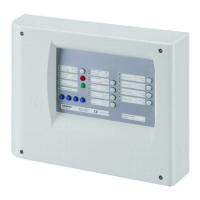
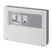
Fig. 13 Indicator elements, housing cover view
KEY2
LD1
LD2
LD3
LD4
LD5
LD6
LD7
LD8
LD9
KEY8KEY9KEY10KEY11KEY12
KEY1
KEY13
KEY14
KEY15
KEY16
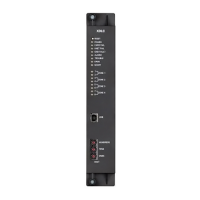
Fig. 14 Indicator elements, XCM1001-2 upper main board view
Indicator elements (LED1 to LED34)
Ref. / Colour Identification State Function
LED1 / Green System ON Lit System in operation (microcomputer is running)
- Mechanical blocking device is in the "Open" position
Lit Mechanical blocking device is in the "Closed" position
LED2 / Yellow Mech. blocked
Fast Mechanical blocking device in wrong position
- - Not used LED3 / Green
Manual only Lit
Alternative (step 10 = option 2):
Triggering by fire detector is blocked, initialized by:
– KEY2 "Mode select"
– Disabling of detector zone 1 or 2
– Switching of detector zone 1 or 2 to "Test mode"
– Monitored inputs 2 and 3 (depending on programming, see steps 4 & 8)
– Control inputs 2 and 3 (depending on programming, see step 15)

 Loading...


