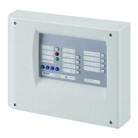
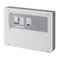
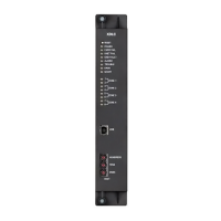
Indicator elements (LED1 to LED34)
Monitored input 1 is in state "Active 2"
Alternative (step 4 = option 2): Monitored input 1 is in state "Inactive 2"
LED14 / Yellow Loss of agent Fast
Alternative (step 4 = option 10): Monitored input 2 is in state "Active 1+2" or
"Inactive 2"
LED15 / Yellow Earth fault Fast A system component has an earth fault
Fast Battery is disconnected or very low charge LED16 / Yellow Power fault
Slow
–
Mains power supply is off (after expiry of the mains delay time) or too low
–
Control input 3 is active (depending on programming, see step15)
LED17 / Yellow Peripheral fault Fast
–
Monitored input 1 line is on open circuit or short circuit
–
Monitored input 2 line is on open circuit or short circuit
–
Monitored control line 3 is on open circuit or short circuit
–
Monitored control line 2 is on open circuit or short circuit if step 3, option 22, 23
or 24 is selected
–
Monitored control line 5 is on open circuit or short circuit or fuse blown if step 1,
option 18, 19 or 21 is selected
–
During calibration processing of monitored control line 5 if step 1, option 18 or
19 is selected
LED18 / Yellow System fault Lit Processor fault (the control unit is not operating)
Lit The unit is in "System test Mode 1" (see chapter 10.7) LED19 / Yellow System test
Slow The unit is in "System test Mode 2" (see chapter 10.7)
Lit
–
Monitored control line 1 is disabled
–
Monitored control line 4 is disabled
–
Monitored control line 2 is disabled if step 3, option 20 or 21 is selected
–
Monitored control line 5 is disabled if step 1, option 14, 15, 16 or 21 is selected
Fast
–
Monitored control line 1 is on open circuit or short circuit
–
Monitored control line 4 is on open circuit or short circuit or fuse blown
–
Monitored control line 2 is on open circuit or short circuit if step 3, option 20 or
21 is selected
–
Monitored control line 5 is on open circuit or short circuit or fuse blown if step 1,
option 14, 15, 16 or 20 is selected
–
During calibration processing of monitored control line 4 and 5
LED20 / Yellow Horn/Actuator
Slow
–
Monitored control line 1 is in state "Horn test" (see chapter 10.4)
–
Monitored control line 1 is in state "Active" in "System test Mode 2" (see
chapter 10.7)
Lit
–
Monitored control line 4 is in state "Active" in "System test Mode 1" (see
chapter 10.7)
–
Calibration processing of monitored control line 4 and 5 is terminated
LED21 / Red -
Slow Monitored control line 4 is in state "Active" in "System test Mode 2" (see chapter
10.7)
Lit – Driver outputs 1, 2, 8 are disabled (depending on programming, see step 16)
– Monitored control line 2 is disabled if step 3, option 18 or 19 is selected
– Monitored control line 5 is disabled if step 1, option 17 is selected
Fast
–
Monitored control line 2 open circuit or short circuit if step 3, option 18 or 19 is
selected
–
Monitored control line 5 open circuit or short circuit or fuse blown if step 1,
option 17 is selected
–
During calibration processing of monitored control line 5 if step 1, option 17 is
selected
LED22 / Yellow Fire control
Slow
–
Monitored control line 3 is in state "Warning panel test"
–
Monitored control line 3 is in state "Active" in "System test Mode 2" (see
chapter 10.7)
Contact 2 is disabled (function may be inoperative) Lit
Alternative (step 13 = option 10):
Automatically activated if access is provided to operating level 2
-
Alternative (step 3 = option 14):
Inoperable, if facility "Remote transmission" not used
LED23 / Yellow RT-fault
Fast Control input 3 or 4 with option "RT-fault" is "Active" (see step 15)
Lit
–
Monitored control line 5 is in state "Active" in "System test Mode 1" (see
chapter 10.7)
–
Calibration processing of monitored control line 4 and 5 is terminated
LED24 / Red -
Slow Monitored control line 5 is in state "Active" in "System Test Mode 2" (see chapter
10.7)
–
Contact 1 is disabled
–
Monitored control line 2 is disabled if step 3, option 17 is selected
Lit
Alternative (step 13 = option 10):
Automatically activated if state operating access 2 is provided
-
Alternative (step 3 = option 14 ):
Inoperable, if facility "Remote transmission" facility not used
LED25 / Yellow RT-alarm
Fast Monitored control line 2 is open circuit or short circuit if step 3, option 17 is
selected
Lit – Monitored input 3 is in state "active 1" (depending on programming, see step 8)

 Loading...


