Argus Radar - INSTALLATION AND SETTINGS
988-10187-004 1.7
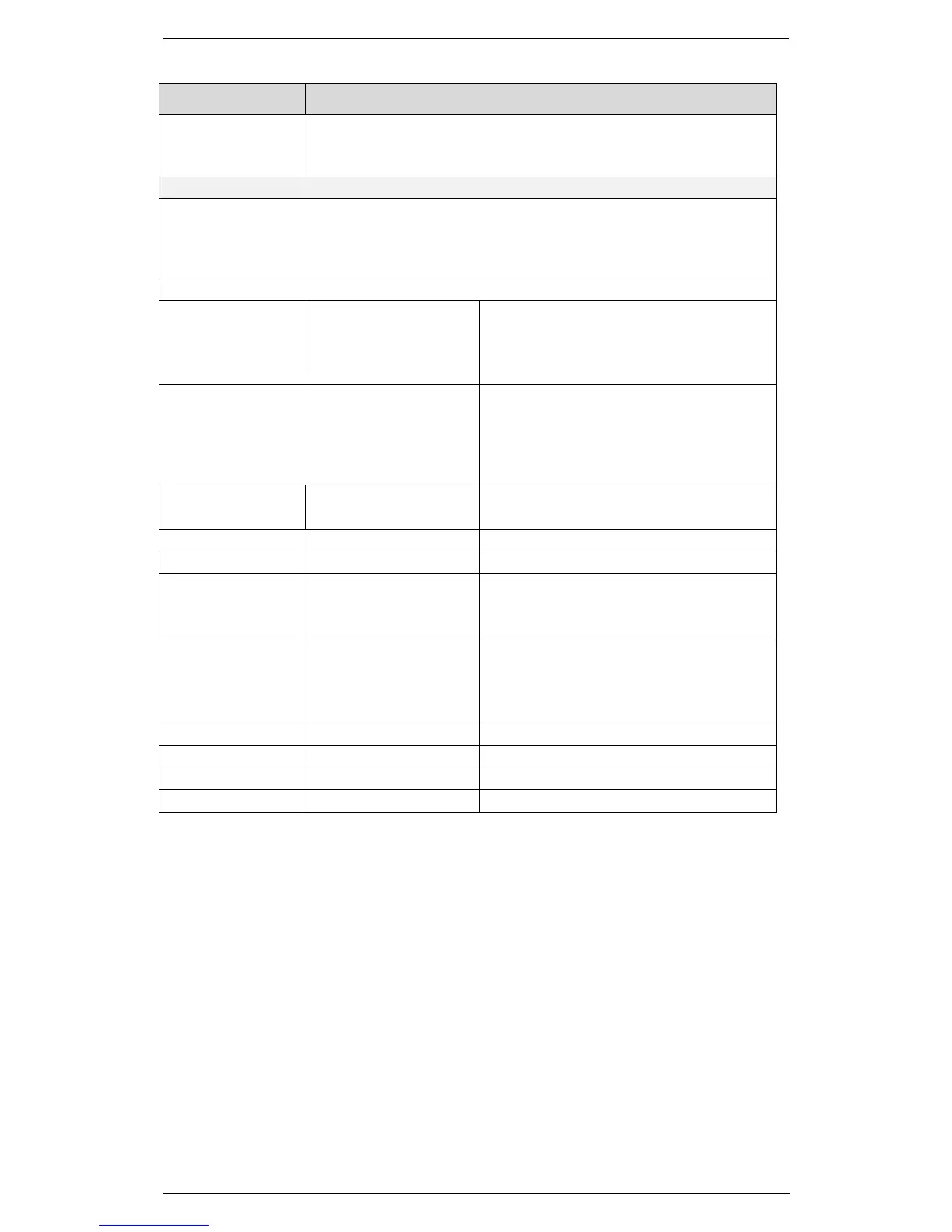
Feature Characteristics
Dead Man Alarm
Reset (DNA)
TB1 (pin 1-2)
Relay output NC/NO
configurable
Active when an action is made on the
control panel
Video and Combined data without
ALPHA Expansion or CH3 and CH4
with this card
. Voltage value: 0,8 to 1,5 Vpp
adjustable
. Load: ≥ 1 KΩ, terminated 75 Ω
Video and data with Alpha Expansion CH1 and CH2: (Optional)
Video:
Amplitude: . 1 to 4 Vpp adjustable
. Load: ≥ 1 KΩ, terminated 75 Ω
. Load: ≥ 1 KΩ, terminated 75 Ω
Serial Interface: Signal Standard:
. RS232 or RS422
. Load: ≥ 3 KΩ, terminated 120 Ω
Antenna Rotation Rotation rate: . 15 to 60 RPM
. Voltage value: 4 to 50 V
. 128 or 132 pulses per antenna revolution
. Load: ≥ 2 KΩ
- Encoder
. Voltage value: 4 to 50 V
. 1024 or 4096 pulses per antenna
revolution
Heading line Voltage value: . 4 to 50 V
Load: . Load: ≥ 2 KΩ
. Positive or negative or bipolar
1.5 Analogue Gyro compass (Synchro or
Stepper)
The gyro signals are connected to TB14 on the Alpha PCB. There are several
connection possibilities depending on type and reference voltage of the gyro.
Refer to the drawing below for the relevant configuration for Synchro and
Stepper.