Argus Radar - INSTALLATION AND SETTINGS
988-10187-004 1.8
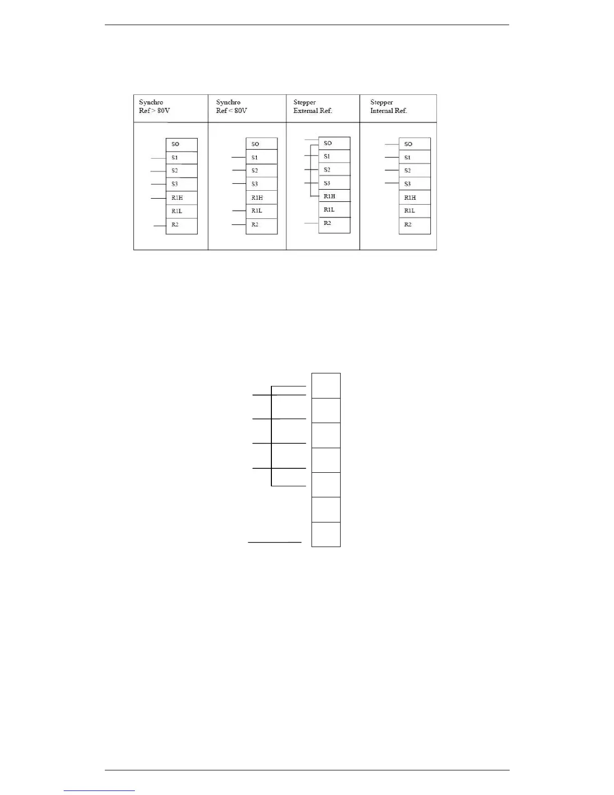
Fig 1 For Argus (ALPHA PCB) connect to TB14.
Note: Connection with stepper gyro full wave rectified signal (SPERRY MK-37,
MK-20)
1. Close the jumpers P10, P13, P15 on the Alpha PCB;
2. make the interconnection to TB4 on the Alpha PCB as follow:
TB14
WIRE
NUMBERS
FROM
GYRO
3. Follow the configuration instructions described in Chapter 3
4. Check the phases status through the LED on the Alpha PCB.
The three phases are given by the gyro with a 3 bit Gray code. The purpose of
this code is to detect the increment of the value and its sign; its most important
characteristic is that only one of the three bits at the time can change and in
this application (normally is not a characteristic of the Gray code), the 3 bits
cannot have all the same level. To give a quick look to the Gray code see the
four green LED on the Alpha:
1. The first one next to red LED is D33 and it indicates the first phase (S1).