Argus Radar - INSTALLATION AND SETTINGS
988-10187-004 1.9
2. The second one is D34 and it is the second phase indicator (S2).
3. The third one is D35 and it indicates the third phase (S3).
4. The last one is D36 and it is to indicate the Reference.
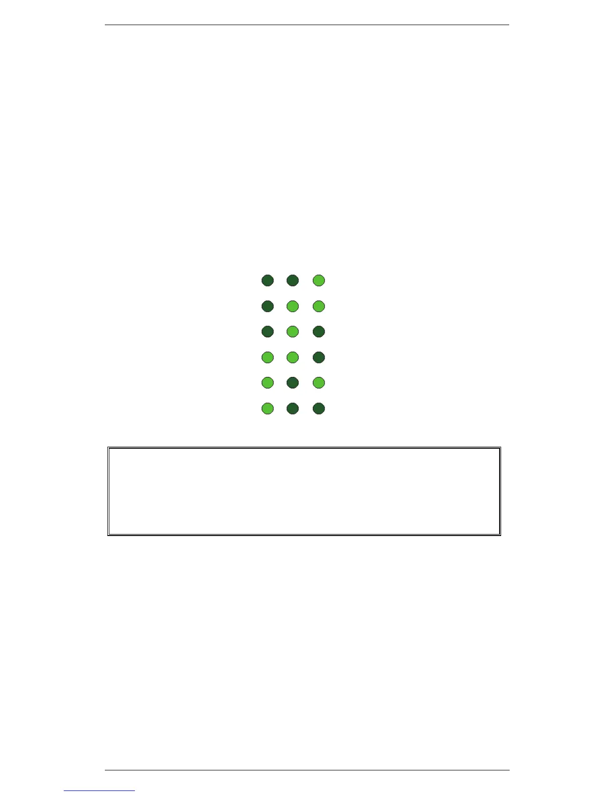
Now that the LEDs are individuated, move the gyro or in any way simulate a
steering and the three LEDs (S1, S2 and S3) will start to change their state and
it will be easy to observe that they will never be “all on” or “all off”; their state will
change one at a time.
WARNING
THE GYRO INTERFACE SHOULD BE CONFIGURED CORRECTLY
ACCORDING TO TYPE OF SENSOR CONNECTED, OTHERWISE
LEVELS AND LED SIGNALS WILL BE INCORRECTLY LIGHTED, ALSO
WHEN THE SIGNALS ARE AVAILABLE.