Boom
3-10
31211015 6036, 6042, 8042, 10042, 10054
6. Using a suitable hoist and slings, lift the boom assembly
and position the boom on the frame. Align the
mounting plates on the frame between the mounting
hubs on each side of the boom assembly. Lower the
boom assembly until the holes in the boom assembly
and the mounting plates align.
7. On the end of the boom pivot pin, closest to the
capscrew hole, mark the capscrew mounting hole
location. Coat the entire pin with anti-seize compound.
8. Insert the pivot pin from the outside of the boom
assembly, making sure the marks for the capscrew
mounting hole stay in line with the capscrew mounting
holes in the boom mounting hub.
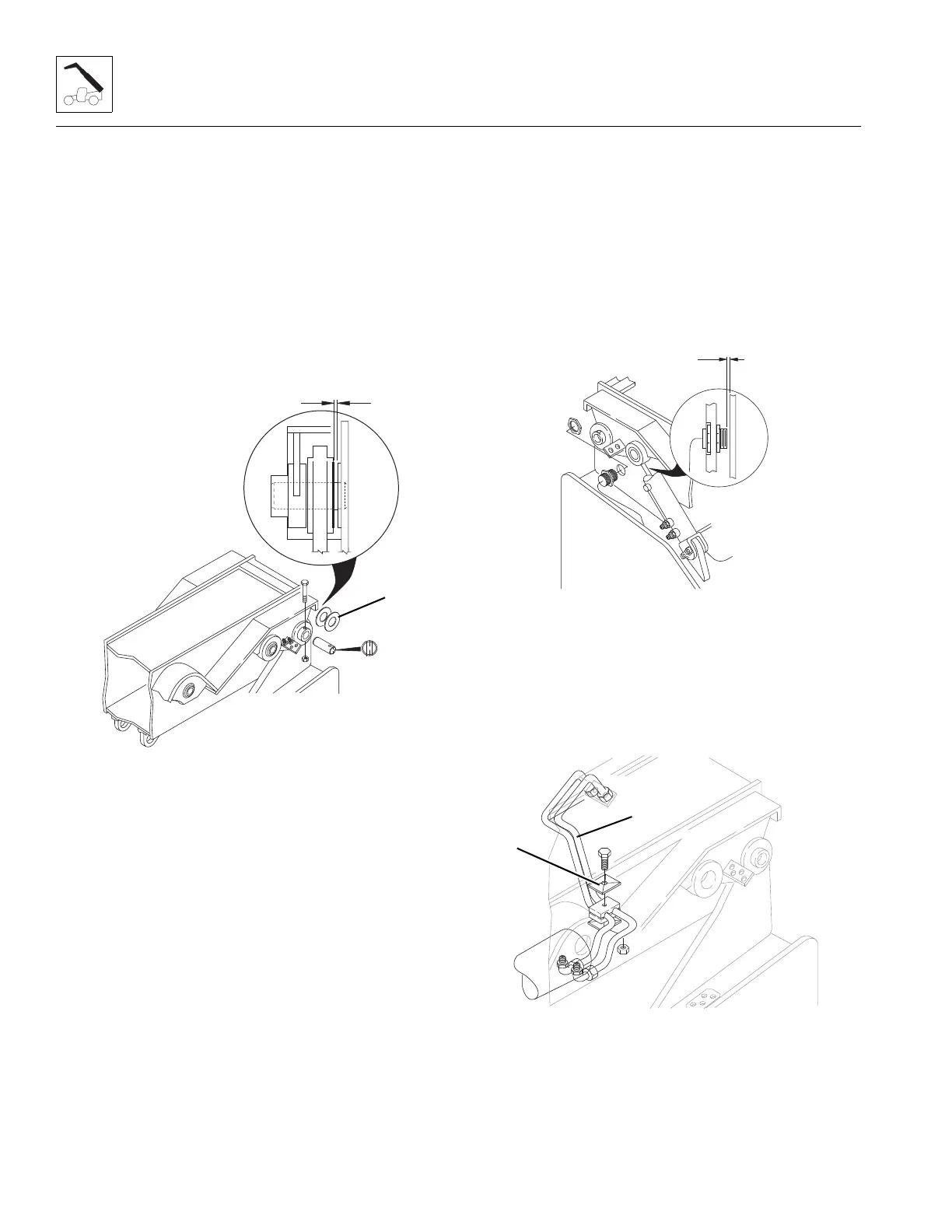
9. Shim the boom as required using the shims (20) to
maintain a 0.10” (2,5 mm) maximum gap (A) between
the boom mounting hub and the self aligning bearing
in the frame. If an additional shim is required to
maintain the maximum gap, the extra shim MUST be
inserted on the right side of the boom.
10. Align the rod end of the right Lift/Lower cylinder with
the self-aligning bearing on the boom assembly. Coat
the entire Lift/Lower cylinder pin with anti-seize
compound. Insert the pin through the rod end of the
cylinder and the self-aligning bearing. Secure with lock
bolt. Repeat procedure with left Lift/Lower cylinder.
11. Use a hoist or suitable support to position the right side
compensation cylinder to its original orientation onto
the lower cylinder mount. Coat the entire
Compensation cylinder pin with anti-seize compound.
Insert the pin through the rod end of the cylinder and
the self-aligning bearing. Secure with lockbolt. Repeat
procedure for left side Compensation cylinder.
12. Install the boom proximity sensor on the right side
mounting plate. With the boom properly shimmed,
position the boom assembly all the way to the right
side.
13. Insert the boom proximity sensor through the hole in
the right side mounting plate. Install the jam nut onto
the boom proximity sensor on the inside of the plate.
Adjust the inner and outer jam nuts on the sensor until
the gap (B) between the sensor and the boom is
0.12 in (3 mm). Torque the inside jam nut to
36 lb-in (4,1 Nm), to hold the sensor in position.
14. Install the Extend and Retract tubes (16) to the inside
bulkhead fitting and the Extend/Retract cylinder.
15. Install the Extend and Retract tube clamp halves (15).
16. Uncap and connect the hydraulic hoses and attach to
their appropriate cylinder locations.