Boom
3-9
6036, 6042, 8042, 10042, 10054 31211015
8. Label, disconnect and cap the hydraulic hoses attached
to both compensation cylinders (17). Cap all fittings to
keep dirt and debris from entering the hydraulic system.
9. Support the compensation cylinder on the right side of
the machine. Remove the rod end pins securing the
cylinder in position. Move the cylinder to a clean, flat
surface. Repeat this procedure for the left side
compensation cylinder.
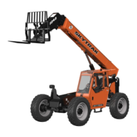
10. Remove the boom proximity sensor (18) from the right
side boom pivot mounting plate.
11. Securely block up or support the right Lift/Lower
cylinder. Remove the rod end pin. Repeat this procedure
for the left Lift/Lower cylinder.
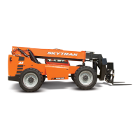
12. Remove the boom pivot pins (19) to the frame. While
removing the pins, note the location and quantity of
shims between the outer boom and frame.
13. Using a sling or suitable support, carefully lift the first
boom section away from the machine. Set the boom
section down on a hard, level surface. Support the
boom as required to allow removal of the Extend/
Retract cylinder from the underside of the boom.
14. Use a hoist and slings to support the Extend/Retract
cylinder. At the base end of the cylinder, remove a
retaining ring from one side of the cylinder base end
pin.
15. Lower the base end of the Extend/Retract cylinder and
remove the rod end of the cylinder from the retainer at
the front of the boom. Place the Extend/Retract cylinder
on a clean, flat surface.
16. At the front of the first boom section, remove rubber
bumper to the Extend/Retract cylinder retainer. Inspect
the rubber bumper. If it is in good condition, the rubber
bumper can be reused. If the bumper is showing signs
of cracking or deterioration, it should be replaced.
17. Remove the two yoke plates to the mount at the front of
the boom. Inspect the yoke plates for wear or distortion.
If any wear or distortion is detected, both plates must
be replaced. If no wear is detected, the plates can
remain assembled to the extend chain clevis.
18. Inspect all wear pads for wear. Refer to Section 3.8,
“Boom Wear Pads”.
3.4.5 First Boom Section Installation
1. On the rear of the boom, assemble the extend and
retract bulkhead fittings to the mounting plate on the
right side. Insert the fittings from the bottom up and
secure in place with the bulkhead fitting nuts on the top
side. Tighten securely. Repeat this procedure for the
attachment tilt fittings on the left side.
Note: Keep the caps on the threaded ends of the fittings to
protect the threads from damage and to keep dirt and debris
from entering the hydraulic system.
2. If equipped with auxiliary hydraulics, assemble the
auxiliary hydraulic bulkhead fittings to the mounting
plate on the left side. Insert the fittings from the bottom
up into the outer set of holes and secure in place with
the bulkhead fitting nuts on the top side. Tighten
securely.
3. Using a sling, position the extend/retract cylinder to its
original orientation under the boom.
4. Coat the base end of the cylinder with anti-seize
compound. Insert the base end cylinder pin through
both mounting ears and the base end of the Extend/
Retract cylinder. Secure the pin in place with a retaining
ring on each side of the pin.
5. Lift the rod end of the Extend/Retract cylinder enough
to insert the threaded stud on the rubber bumper into
the hole in the Extend/Retract cylinder retainer. Secure
the rubber bumper in place with a locknut. Tighten
securely. Lower the rod end of the Extend/Retract
cylinder, and allow it to rest on the rubber bumper.
 Loading...