Hydraulic Section
8-48
31211015 6036, 6042, 8042, 10042, 10054
c. Secondary Function Manifold Installation
1. Place the secondary function manifold into position on
the mounting plate on the machine frame.
2. Install bolt and nut securing valve to frame.
3. Connect all the previously labeled hydraulic hoses,
fittings, solenoid wire terminal leads, etc., to the
secondary function manifold.
4. Check the routing of all hoses and wiring for sharp
bends or interference with any rotating members, and
install tie wraps and/or protective conduit as required.
Tighten all hose clamps.
5. Properly connect the battery. Refer Section 9.8,
“Battery”, for procedure.
6. Remove the Do Not Operate Tags from both the ignition
key switch and the steering wheel.
7. Start the engine and run at approximately
1/3 - 1/2 throttle for about one minute without moving
the machine or operating any hydraulic functions.
8. Inspect for leaks and check the level of the hydraulic
fluid in the reservoir. Shut the engine OFF.
Note: Check for leaks and repair as required before continuing.
Add hydraulic fluid to reservoir as needed.
9. Wipe up any hydraulic fluid spillage in, on, near and
around the machine, work area and tools.
10. Install the transmission covers.
11. Close and secure the engine cover.
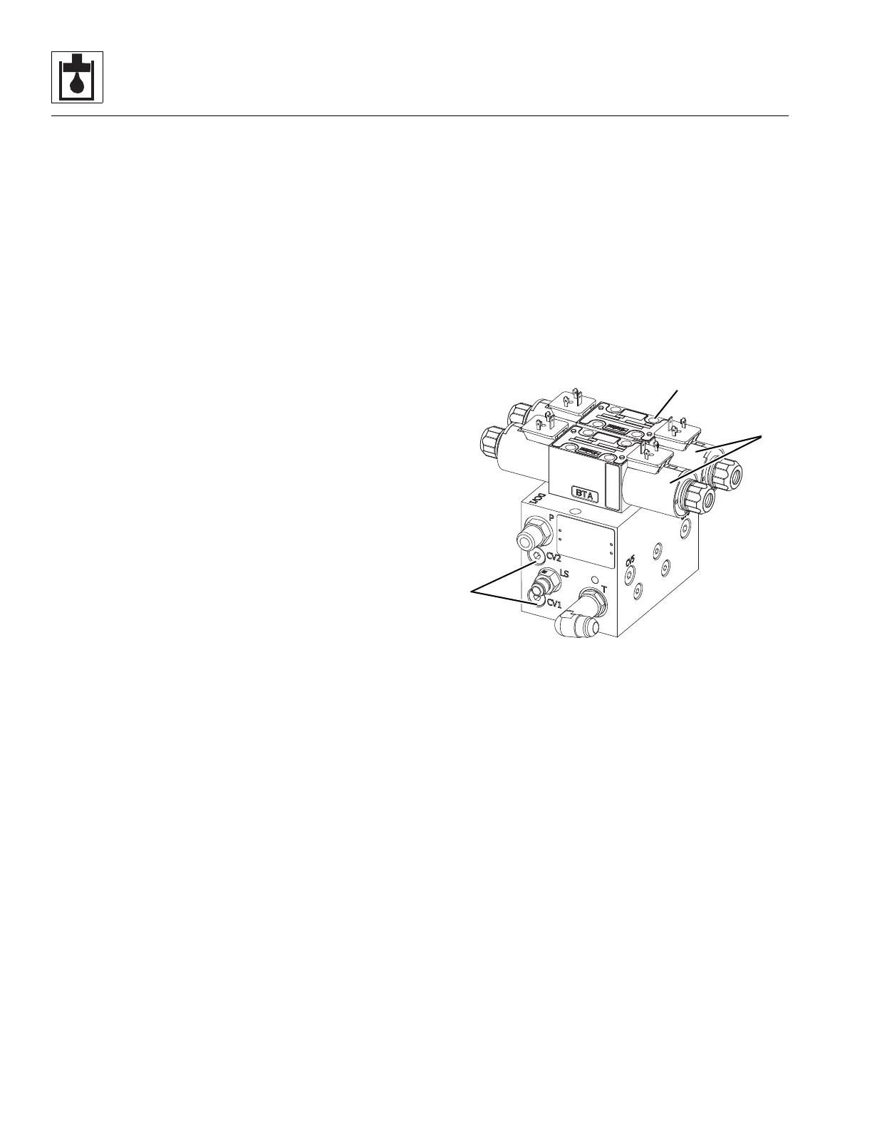
8.8.9 Outrigger Valve (10042 & 10054 only)
The outrigger valve allows the left and right outriggers to be
raised or lowered depending on the position of the outrigger
switches located on the side console in the cab.
Verify the correct operation of the outrigger valve solenoids
before considering replacement of the valve.
a. Outrigger Valve Removal
1. Park the machine on a firm, level surface, level the
machine, fully retract the boom, raise the boom, place
the transmission in (N) NEUTRAL, engage the park brake
and shut the engine OFF.
2. Place a Do Not Operate Tag on both the ignition key
switch and the steering wheel, stating that the machine
should not be operated.
3. Temporarily block up or support the raised boom.
4. Open the engine cover. Allow the system fluids to cool.
5. Properly disconnect the battery. Refer Section 9.8,
“Battery”, for procedure.
6. Remove the transmission covers.
7. Label, disconnect and cap the hydraulic hoses and the
electrical plugs connected to the outrigger valve.
8. Remove the two flange nuts and two carriage bolts
securing the outrigger valve to the frame. Remove the
outrigger valve from the machine.
9. Wipe up any hydraulic fluid spillage in, on, near and
around the machine, work area and tools.
b. Outrigger Valve Disassembly, Cleaning, Inspection
and Assembly
1. Place the outrigger valve assembly on a suitable work
surface.
2. Remove the solenoid valve assemblies (2) from the
outrigger valve by removing the four capscrews (3).
Discard the four o-rings.
3. Remove four shuttle cartridges (4) from outrigger valve.
CV3 and CV4 are located on the opposite end of the
valve body.
4. Clean all components with a suitable cleaner
before inspection.
5. Inspect the solenoid cartridges for proper operation.
Check by shifting the spool to ensure that it is
functioning properly. Check that the spring is intact.
Inspect the cartridge interior for contamination.
6. Inspect internal passageways of the outrigger
valve for wear, damage, etc. If inner surfaces of the valve
DO NOT display an ultra-smooth, polished finish, or
components are damaged in any way, replace the valve
or appropriate part. Often, dirty hydraulic fluid causes
failure of internal seals and damage to the polished
surfaces within the valve block.