Hydraulic Section
8-49
6036, 6042, 8042, 10042, 10054 31211015
Note: ALWAYS replace seals, o-rings, gaskets, etc., with new
parts to help ensure proper sealing and operation. Lubricate
seals and o-rings with clean hydraulic oil.
7. Install the shuttle cartridges into the outrigger valve.
Torque to 35 lb-ft (48 Nm).
8. Attach the solenoid assemblies to the outrigger valve
using four new, oiled o-rings and the previously used
capscrews.
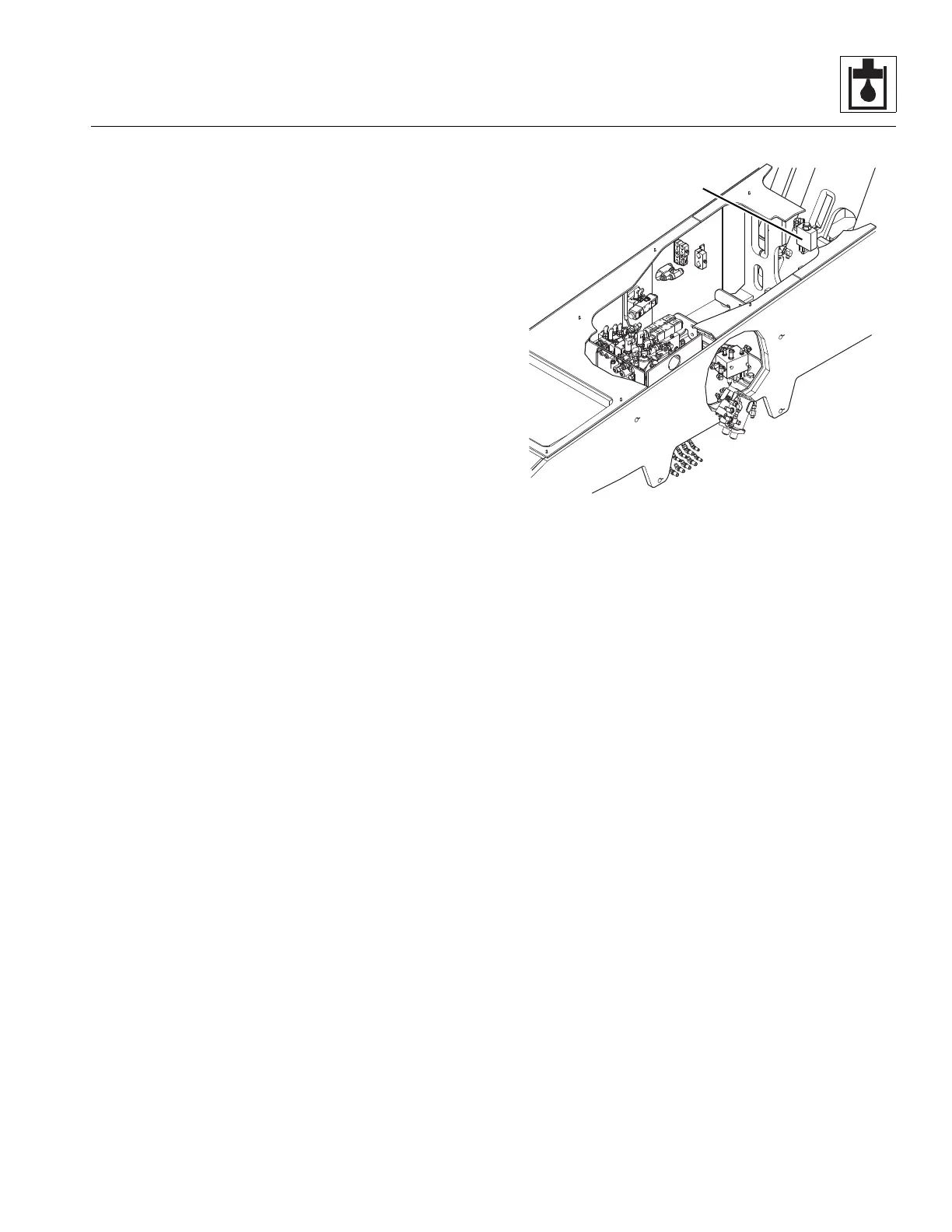
c. Outrigger Valve Installation
1. Insert the previously used bolts through the bottom of
the outrigger valve and loosely attach the flange nuts to
the carriage bolts.
2. Position the outrigger valve so that the heads of the
carriage bolts go through the slots in the frame. Tighten
the flange nuts.
3. Connect all the previously labeled hydraulic hoses,
fittings, solenoid wire terminal leads, etc., to the
outrigger valve.
4. Check the routing of all hoses and wiring for sharp
bends or interference with any rotating members, and
install tie wraps and/or protective conduit as required.
Tighten all hose clamps.
5. Properly connect the battery. Refer to Section 9.8,
“Battery”, for procedure.
6. Remove the Do Not Operate Tags from both the ignition
key switch and the steering wheel.
7. Start the engine and run at approximately
1/3 - 1/2 throttle for about one minute without moving
the machine or operating any hydraulic functions.
8. Inspect for leaks and check the level of the hydraulic
fluid in the reservoir. Shut the engine OFF.
Note: Check for leaks and repair as required
before continuing. Add hydraulic fluid to the reservoir
as needed.
9. Wipe up any hydraulic fluid spillage in, on, near and
around the machine, work area and tools.
10. Install the transmission covers.
11. Close and secure the engine cover.
8.8.10 Extend Lockout Valve (10054 only)
Model 10054 has an extend lockout valve (5) which prevents
the boom from being extended beyond 42 feet unless the
outriggers are lowered onto firm terrain. Once the outriggers
are lowered, pressure switches located on each outrigger
cylinder close and energize the solenoid on the boom extend
lockout valve. The boom can then be fully extended.
a. Extend Lockout Valve Removal
1. Park the machine on a firm, level surface, level the
machine, fully retract the boom, raise the boom, place
the transmission in (N) NEUTRAL, engage the park brake
and shut the engine OFF.
2. Place a Do Not Operate Tag on both the ignition key
switch and the steering wheel, stating that the machine
should not be operated.
3. Temporarily block up or support the raised boom.
4. Open the engine cover. Allow the system fluids to cool.
5. Properly disconnect the battery. Refer Section 9.8,
“Battery”, for procedure.
6. Remove the transmission covers.
7. Label, disconnect and cap hydraulic hoses and electrical
plugs connected to extend lockout valve.
8. Remove nut and bolt securing extend lockout valve to
the frame. Remove the valve from the machine.
9. Wipe up any hydraulic fluid spillage in, on, near and
around the machine, work area and tools.