Cab and Covers
4-13
6036, 6042, 8042, 10042, 10054 31211015
4.4 CAB REMOVAL
Note: To help ensure safety and optimum performance,
replace the cab if it is damaged. Refer to the appropriate parts
manual for ordering information.
Inspect the cab, its welds and mounts. If modification,
damage, a cracked weld and/or fatigued metal is discovered,
replace the cab. Contact the local JLG dealer with any
questions about the suitability or condition of a cab.
Note: Remove and label cab components as needed before
removing the cab from the machine. Label, disconnect and cap
hydraulic hoses. Transfer cab parts to the replacement cab after
the replacement cab is securely mounted on the machine.
1. Park the machine on a firm, level surface. Allow
sufficient overhead and side clearance for cab removal.
Level the machine, fully retract the boom, lower the
boom, place the transmission in (N) NEUTRAL, engage
the park brake and shut the engine OFF.
2. Block all four wheels to help prevent the machine from
moving. Assure that there is sufficient overhead and
side clearance for cab removal.
3. Open the engine rear and side engine doors. Allow the
system fluids to cool.
4. Properly disconnect the battery. Refer Section 9.8,
“Battery”, for procedure.
5. Place a suitable container beneath the radiator drain
plug or petcock. Slowly turn the radiator cap to the first
stop and allow any pressure to escape. Remove the
radiator cap.
6. Place a funnel at the base of the radiator to channel the
drained coolant into the container. Loosen the drain
plug or petcock and allow the coolant to drain.
7. Transfer the coolant to a container with a cover, and
label as “Used Antifreeze”. Dispose of the used coolant
at an approved recycling facility.
8. Close the radiator drain plug or petcock.
9. Remove the transmission covers.
10. Remove the heater access panel. If equipped, Label,
disconnect and cap the cab heater hoses. Refer to
Section 4.3.8, “Heater System (if equipped)”.
11. Remove the console panel in the cab.
12. Label and disconnect the electrical connections. Push
the connectors through the opening at the bottom of
the cab.
13. Remove the frame level and auxiliary lever assemblies
from the main control valve. Refer to Section 4.3.6,
“Auxiliary/Frame Level Lever Assemblies”.
14. Label, disconnect and cap all hydraulic hoses. Refer to
Section 4.3.5, “Joystick Assembly”. Cap all fittings to
keep dirt and debris from entering the hydraulic system.
Push the hoses through the opening at the bottom of
the cab.
15. If necessary, remove mirrors and other cab components
that may become damaged during cab removal.
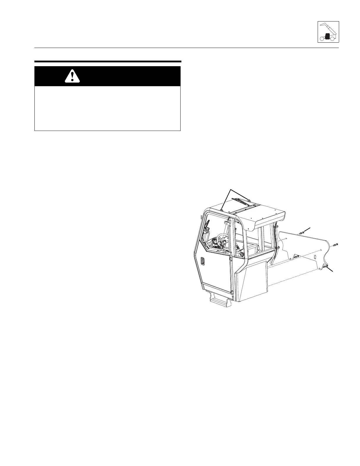
16. Attach a clevis to each of the cab lifting brackets (1).
Route a sling with a minimum lifting capacity of
1000 lb (453 kg) to a hoist or overhead crane. Center the
sling to ensure even lifting.
17. Remove the two upper cab-to-frame capscrews and
two flat washers (2).
18. Remove the two lower cab-to-frame capscrews and two
flat washers (2).
19. Carefully begin to lift the cab. Stop and check that all
wiring, hydraulic hoses and fasteners are disconnected
and removed.
WARNING
The protection offered by this ROPS/FOPS will be
impaired if subjected to any modification or structural
damage, at which time replacement is necessary.
ROPS/FOPS must be properly installed using fasteners of
correct size and grade, and torqued to their specified
value.


 To Next Page