Cab and Covers
4-11
6036, 6042, 8042, 10042, 10054 31211015
4.3.9 Heater and A/C System (if equipped)
a. Removal
1. Park machine on a firm, level surface, level machine,
fully retract boom, lower boom, place transmission in
(N) NEUTRAL, engage park brake and shut engine OFF.
2. Place a Do Not Operate Tag on both ignition key switch
and steering wheel.
3. Open engine covers. Allow system fluids to cool.
4. Properly disconnect the battery. Refer Section 9.8,
“Battery”, for procedure.
5. Place a suitable container beneath radiator. Slowly turn
surge tank cap and allow any pressure to escape.
Remove surge tank cap.
6. Place a funnel at base of radiator to channel drained
coolant into container. Remove drain plug and allow
coolant to drain.
7. Transfer coolant to a container with a cover, and label as
“Used Coolant”. Dispose of used coolant at an approved
recycling facility.
8. Tighten radiator drain plug.
9. Drain the refrigerant from the air conditioning system.
Note: The local JLG dealer or certified air conditioning service
center or personnel to perform the refrigerant removal from the
system.
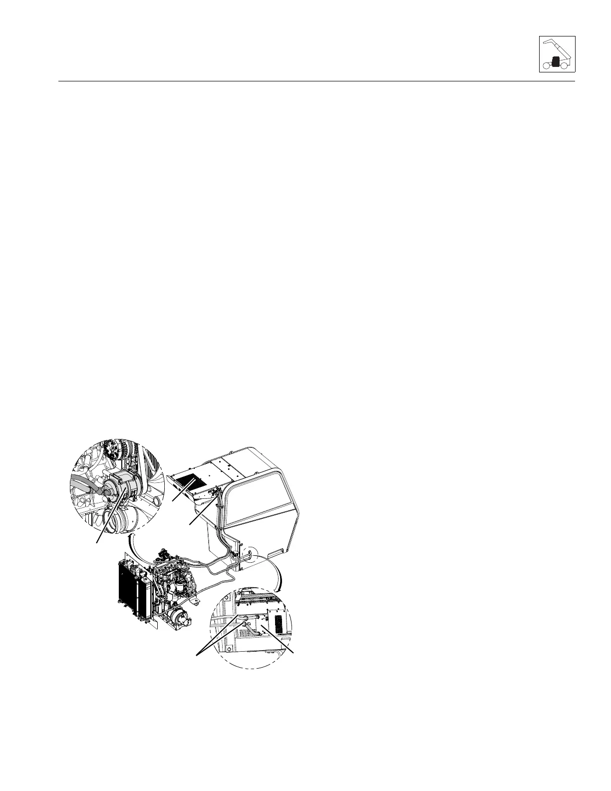
10. Label and disconnect hoses (41) attached to the
condenser assembly (42).
11. Label and disconnect all electrical connections attached
to the condenser assembly (42).
12. Remove bolts securing the condenser assembly (42) to
cab roof. Remove condenser assembly from rear of the
cab roof.
13. Label and disconnect all electrical connections attached
to the heater and air conditioning assembly (43).
14. Label and remove hoses (44) connected to the heater
and air conditioning assembly (43).
15. Label and disconnect air conditioning hoses attached to
heater assembly.
16. Remove bolts securing heater assembly to cab. Remove
heater assembly.
17. Label and disconnect air conditioning hoses attached to
compressor (45).
18. Remove hardware securing compressor to engine.
Remove compressor (45).
b. Installation
1. Install cab condenser assembly (42) to cab roof. Secure
with previously removed hardware.
2. Connect previously labeled electrical connections to
the condenser assembly (42).
3. Connect previously labeled hoses (24) to condenser
assembly (42).
4. Position heater and air conditioning assembly (43) to
original orientation to cab. Secure with previously
removed hardware.
5. Connect previously labeled electrical connections to
heater and air conditioning assembly.
6. Connect previously labeled heater hoses to appropriate
locations.
7. Connect previously labeled air conditioning hoses to
appropriate locations.
8. Connect previously labeled air conditioning hoses
attached to compressor (45).
9. Install compressor (45) to engine.
10. Fill cooling system completely with coolant, allowing
time for the coolant to fill the engine block. The cooling
system capacity is listed in Section 2.3, “Fluid and
Lubricant Capacities”.
11. Fill air conditioning system completely with refrigerant.
Refer Section 2.3, “Fluid and Lubricant Capacities”, for
refrigerant type and capacity.
Note: Ensure that the petcock is closed for vehicle equipped
with a cab heater, when one liter of coolant is drained from
system and all air is purged.


 To Next Page