Stabil-TRAK™ System and Boom Interlock System
10-7
6036, 6042, 8042, 10042, 10054 31211015
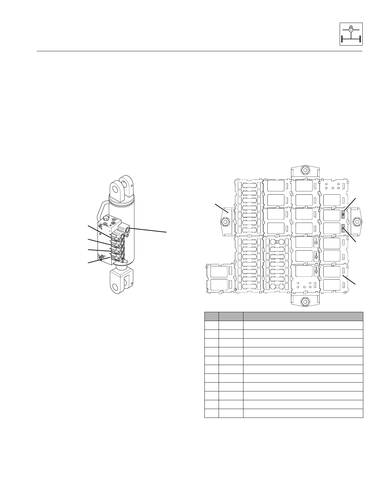
10.4.2 Stabil-TRAK™ Solenoid Valves
There are five Stabil-TRAK solenoid valves installed in the Stabil-
TRAK manifold, attached to the stabilizer cylinder above the
left side of the rear axle.
If a solenoid valve is suspected of malfunctioning, disconnect
the coil wiring lead and test the coil for proper resistance (7-
9 ohms) and for proper voltage from the harness (12 VDC).
Replace the solenoid coil if open or shorted to ground.
Also inspect the valve cartridge, o-rings, and the other
hydraulic and electrical components in the circuit to accurately
determine the cause of the problem.
All solenoid coils are identical and can be interchanged for
diagnostic purposes.
Note: DO NOT interchange solenoid valves 4A (14), 4B (15),
12A (16) or 12B (17) with solenoid valve 3 (18). These valves will
fit into the other locations, but are configured differently
internally and will not operate properly if interchanged.
Cartridge valves 4A (14), 4B (15), 12A (16) and
12B (17) are identical and can be interchanged for diagnostic
proposes.
Note: Make sure 0.060 orifices are in place when installing
solenoid valves 4A (14) and 4B (15).
In general, if there is a problem with the Stabil-TRAK system
beyond common electrical troubles, the involved electrical
and hydraulic circuits should each be checked and the exact
source of the problem diagnosed before any parts are
replaced.
10.4.3 Logic Wiring Harness (10054 Only)
The Model 10054 uses an additional logic wiring harness,
that includes all wiring, fuses and relays needed for the
operation of the boom interlock, Stabil-TRAK and outrigger
systems.
The logic harness has a fuse panel (1) that is attached to the
fuse panel (2) from cab harness. The logic harness includes all
the additional relays (R14 through R20) and fuses (24 and
25) required for the operation of the boom interlock, Stabil-
TRAK and outrigger systems.
Refer to Section 10.9, “Stabil-TRAK Boom Interlock Electrical
Circuit Operation and Troubleshooting (10054),” for
electrical troubleshooting information.
No. Amp Circuit
4 10 Amp Boom Switch
R1 35 Amp Boom Switch
R16 35 Amp Stabilizer Interlock
R17 35 Amp Stabilizer Lockup
R18 35 Amp Boom Extend Interlock Relay
R19 35 Amp Right Outrigger Lock Out
R20 35 Amp Left Outrigger Lock Out
R21 35 Amp Park Brake Interlock Relay
R22 35 Amp Boom Extension Lock Out
24 7.5 Amp Outrigger 1 (Mini-Fuse)
25 7.5 Amp Outrigger 2 (Mini-Fuse)
MAQ1911
R16
R1
R17
R18
R19
R20
R21
R22
4