Electrical System
9-27
6036, 6042, 8042, 10042, 10054 31211015
11. Remove the control panel from the panel.
b. Disassembly
DO NOT disassemble the cab heater and fan controls. The
controls are not serviceable. Replace controls if found to be
defective.
c. Installation and Testing
1. Check that the variable speed fan control is in the OFF
position.
2. If installing the temperature control, attach the control
cable to the back of the control.
3. Insert the control shaft through the panel, ensuring that
the knob is in the VERTICAL position.
4. Install the locknut on the shaft and tighten.
5. Connect the cab harness connector to the variable
speed fan control.
6. Install the screws and backing locknuts securing the
control panel to the dash panel.
7. Install the setscrew securing the knob to the control.
8. Install the right side control panel.
9. Properly connect the battery. Refer Section 9.8,
“Battery”, for procedure.
10. Remove the Do Not Operate Tags from both the ignition
key switch and the steering wheel.
11. Turn the ignition key to the ON position and check the
fan speeds. If further repair is needed, refer to Section
9.5, “Electrical System Schematics”.
12. Start the machine and allow engine to warm to
operating temperature. Check heat control at different
levels.
13. Close and secure the engine rear and side engine doors.
9.12 SOLENOIDS, SENSORS AND SENDERS
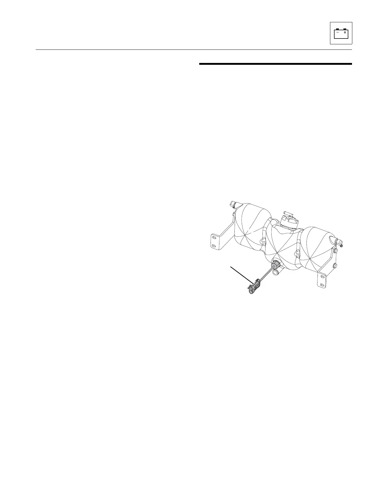
9.12.1 Coolant Level Sensor
a. Coolant Level Sensor Removal
1. Park machine on a firm, level surface, level machine,
fully retract boom, raise the boom, place transmission in
(N) NEUTRAL, engage the park brake and shut the
engine OFF.
2. Place a Do Not Operate Tag on both ignition key switch
and steering wheel, stating that machine should not be
operated.
3. Open the engine rear and side engine doors. Allow the
system fluids to cool.
4. Temporarily block up or support the boom.
5. Properly disconnect the battery. Refer Section 9.8,
“Battery”, for procedure.
6. Label and disconnect the wiring connector from the
Coolant Level Sensor (8).
7. Unthread switch from surge tank.
b. Coolant Level Sensor Disassembly
DO NOT disassemble the Coolant Level Sensor. Replace a
defective switch with a new part.
c. Coolant Level Sensor Installation
1. Thread switch into engine. Tighten securely.
2. Connect previously labeled wiring connector
to switch.
3. Properly connect the battery. Refer Section 9.8,
“Battery”, for procedure.
4. Remove the Do Not Operate Tags from both the ignition
key switch and the steering wheel.