Cab and Covers
4-6
31211015 6036, 6042, 8042, 10042, 10054
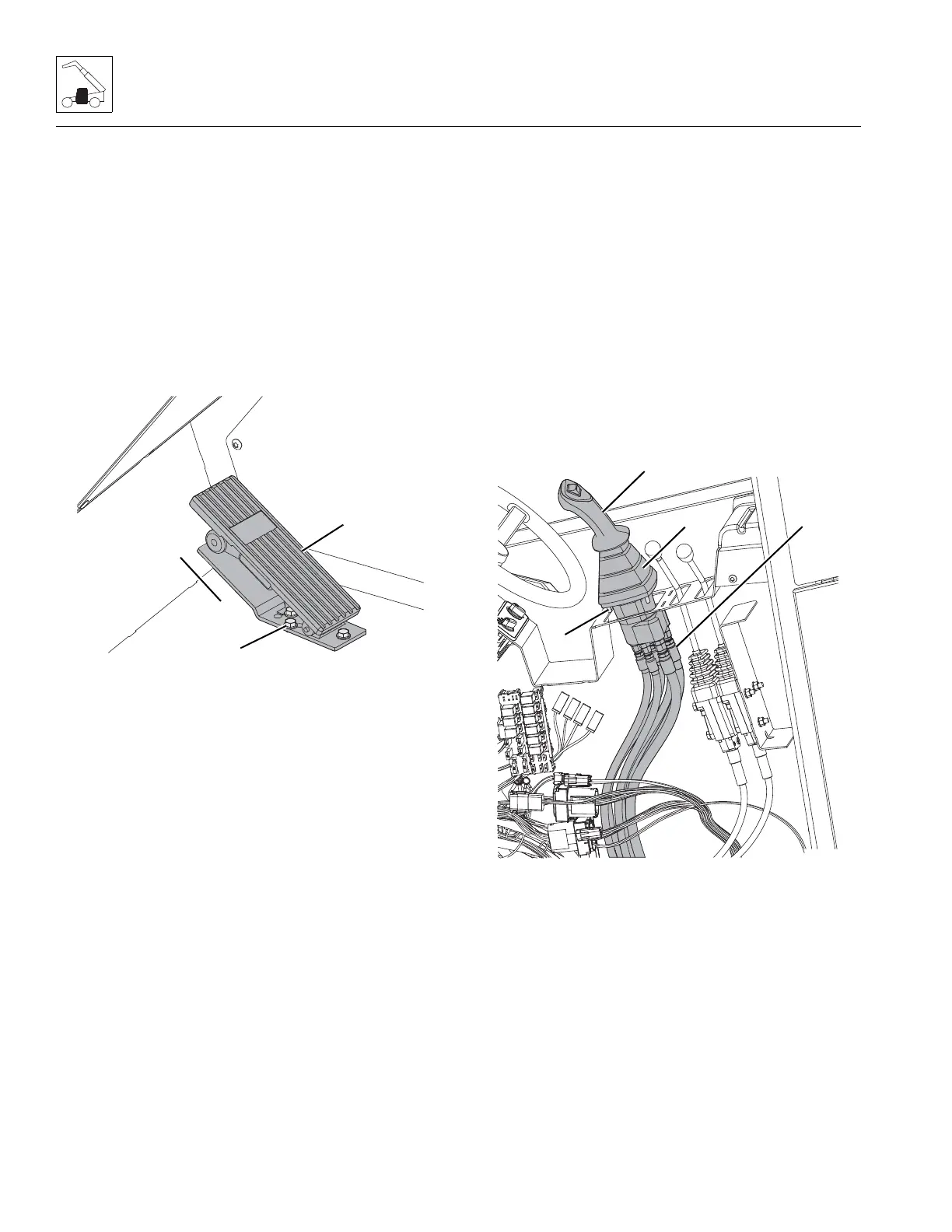
4.3.4 Throttle Pedal
a. Throttle Pedal Removal
1. Park the machine on a firm, level surface, level the
machine, fully retract the boom, lower the boom, place
the transmission in (N) NEUTRAL, engage the parking
brake and turn the engine OFF.
2. Place a Do Not Operate Tag on both the ignition key
switch and steering wheel, stating that the machine
should not be operated.
3. Properly disconnect the battery. Refer Section 9.8,
“Battery”, for procedure.
4. Remove the bolts (11) securing the throttle pedal to the
cab floor (12).
5. Disconnect the electrical harness connector (13) from
the back side of the throttle pedal.
6. Remove the throttle pedal assembly from the cab.
b. Throttle Pedal Installation
1. Position the throttle pedal in its mounting location
within the cab.
2. Reconnect the wire harness plug to the backside of the
throttle pedal.
3. Secure the throttle pedal in place with previously used
hardware.
4. Properly connect the battery. Refer Section 9.8,
“Battery”, for procedure.
5. Remove the Do Not Operate Tags from both the ignition
key switch and the steering wheel.
4.3.5 Joystick Assembly
These removal and installation instructions apply to the
hydraulic joystick.
a. Joystick Assembly Removal
1. Park the machine on a firm, level surface, level the
machine, fully retract the boom, lower the boom, place
the transmission in (N) NEUTRAL, engage the parking
brake and turn the engine OFF.
2. Place a Do Not Operate Tag on both the ignition key
switch and steering wheel, stating that the machine
should not be operated.
3. Properly disconnect the battery. Refer Section 9.8,
“Battery”, for procedure.
4. Remove the console panel in the cab.
Note: Label all hydraulic hoses to ensure correct installation.
5. Label, disconnect and cap the hydraulic hoses (14)
attached to joystick (15).
6. Disconnect the tilt function electrical connector.
7. Lift the joystick’s rubber sleeve (16), remove the
bolts (17) securing the boom joystick to the cab.
8. Remove the joystick assembly.


 To Next Page