Cab and Covers
4-8
31211015 6036, 6042, 8042, 10042, 10054
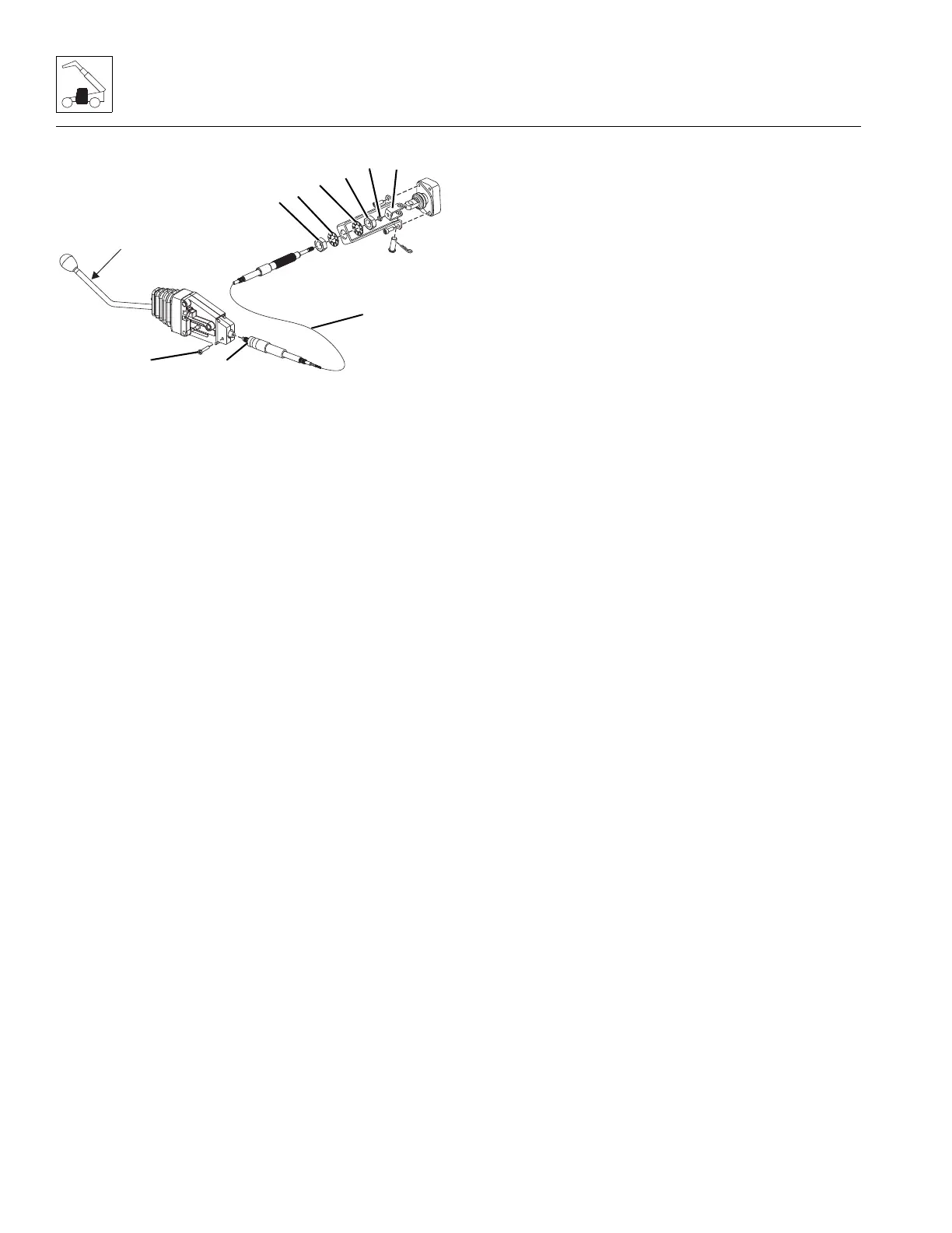
b. Cable Removal
1. Disconnect control cable (22) at the lever control:
a. Remove the bolt (23) securing the control cable.
b. Push the control lever to expose the cable nut. Use a
wrench on the flats to loosen the cable nut (24).
c. Remove the cable.
2. Mark the location of the adjusting nuts (25) on the main
control valve end of the control cable.
3. Loosen lock nut (26) and remove clevis (27).
4. Remove adjusting nuts (26) and washers (28).
c. Cable Installation
1. Install one adjusting nut (25), and washer (28) on the
control cable (22).
2. Install cable bracket (21) onto the control cable (22).
3. Install washer (28), nut (25), lock nut (26) and clevis (27)
onto the control cable (22).
DO NOT tighten the adjusting nuts at this time.
4. Connect control cable (22) at the lever control:
a. Push the control lever and install the control cable.
b. Use a wrench on the flats to hold the slider head,
and tighten the cable nut (24).
c. Install the bolt (23) securing the control cable.
d. Lever Assembly Installation
1. Secure the lever assembly(s) to the cab with the
previously used hardware.
2. Secure the control cable(s) bracket to the main control
valve with the previously removed hardware.
3. Center the control levers and tighten the adjusting
nuts (25) as required.
4. Install the previously removed knobs on each lever
assembly.
5. Properly connect the battery. Refer Section 9.8,
“Battery”, for procedure.
6. Test the lever(s) function:
Frame Level Lever:
• Move rear lever to right, activating frame level function.
The machine should move RIGHT.
• Move rear lever to left, activating frame level function.
The machine should move LEFT.
Auxiliary Lever:
• Move the front leverto the right, the auxiliary
attachment should LOWER/OPEN.
• Move the front lever to the left, the auxiliary attachment
should RAISE/CLOSE.
7. Install console panel in the cab.
8. Remove the Do Not Operate Tags from both the ignition
key switch and the steering wheel.
4.3.7 Windshield Wiper Assembly
Refer to Section 9.10, “Window Wiper/Washer Windshield
Wiper Motor”, for removal and installation information.
4.3.8 Heater System (if equipped)
Note: If machine is equipped with air conditioning, DO NOT
loosen or disconnect any air conditioning hoses until the air
conditioning system has been properly drained by the local JLG
dealer or certified air conditioning service center.
a. Cab Heater Assembly Removal
1. Park the machine on a firm, level surface, level the
machine, fully retract the boom, lower the boom, place
the transmission in (N) NEUTRAL, engage the park brake
and shut the engine OFF.
2. Place a Do Not Operate Tag on both the ignition key
switch and the steering wheel, stating that the machine
should not be operated.
3. Open the engine rear and side engine doors. Allow the
system fluids to cool.
4. Properly disconnect the battery. Refer Section 9.8,
“Battery”, for procedure.
5. Place a suitable container beneath the radiator drain
plug or petcock. Slowly turn the radiator cap to the first
stop, and allow any pressure to escape. Remove the
radiator cap.
6. Place a funnel at the base of the radiator to channel the
drained coolant into the container. Loosen the drain
plug or petcock and allow the coolant to drain.
7. Transfer the coolant to a container with a cover, and
label as “Used Antifreeze”. Dispose of the used coolant
at an approved recycling facility.


 To Next Page