Electrical System
9-28
31211015 6036, 6042, 8042, 10042, 10054
5. Start engine. Allow it to reach operating temperature
and observe the operator instrument cluster for
warning indication. If switch is not defective, problem
could be elsewhere; possibly in a shorted wire,
improper running engine, improper or low coolant,
obstructed or faulty radiator, coolant pump, loose fan
belt, defective instrument cluster, etc.
6. Close and secure the engine rear and side engine doors.
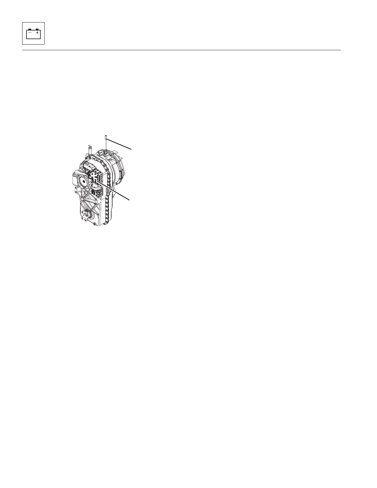
9.12.2 Transmission Solenoid Valves
Note: If the transmission is not shifting properly, the
transmission shift control switch (travel select lever), wiring
harness or transmission shift solenoids (10) should be
checked in order to determine which component is
defective. Specific information to determine which travel
position and corresponding component is not responding
can be found in the detailed transmission service
instructions (covering repair, disassembly, reassembly and
adjustment information) are provided in the
ZF 4 WG-98 TC Repair Manual P/N 5871 135 002
(JLG P/N 8990455). and can be obtained by calling your local
Authorized Service Department.
The transmission should be checked, serviced and repaired
only by experienced service technicians who are aware of all
safety instructions and particular component features.
Note: Contact your local authorized Service Department if
internal transmission repair is required during the warranty
period.
9.12.3 Transmission Temperature Sender
a. Transmission Temperature Sender Removal
The transmission temperature sender (11) is threaded into
the top of the transmission housing.
1. Park machine on a firm, level surface, level machine,
fully retract boom, lower boom, place transmission in
(N) NEUTRAL, engage parking brake, and shut engine
OFF.
2. Place a Do Not Operate Tag on both the ignition key
switch and the steering wheel, stating that the machine
should not be operated.
3. Properly disconnect the battery. Refer Section 9.8,
“Battery”, for procedure.
4. Temporarily block up or support the boom.
5. Open the engine rear and side engine doors. Allow the
system fluids to cool.
6. Remove the transmission covers.
7. Unplug the transmission temperature sender connector
from the wiring harness connector.
8. The sender is threaded into the transmission housing.
Remove the sender.
b. Transmission Temperature Sender Inspection and
Replacement
Inspect the sender and the wiring harness connector
terminals for continuity. Replace a defective or faulty sender
with a new part.
c. Transmission Temperature Sender Installation and
Testing
1. Thread the transmission temperature sender into the
transmission housing snugly, then connect the sender
connector to the wiring harness connector.
2. Properly connect the battery. Refer Section 9.8,
“Battery”, for procedure.
3. Remove the Do Not Operate Tags from both the ignition
key switch and the steering wheel.
4. Check for proper fluid level.
5. Start the engine, allow it to reach operating
temperature and observe the operator display cluster
for warning indication. If the sender is not defective, the
problem could be elsewhere; possibly in a shorted wire,
damaged transmission, improper or low fluid, etc.
6. Install the transmission covers.
7. Close and secure the engine rear and side engine doors.