General Information and Specifications
2-36
31211015 6036, 6042, 8042, 10042, 10054
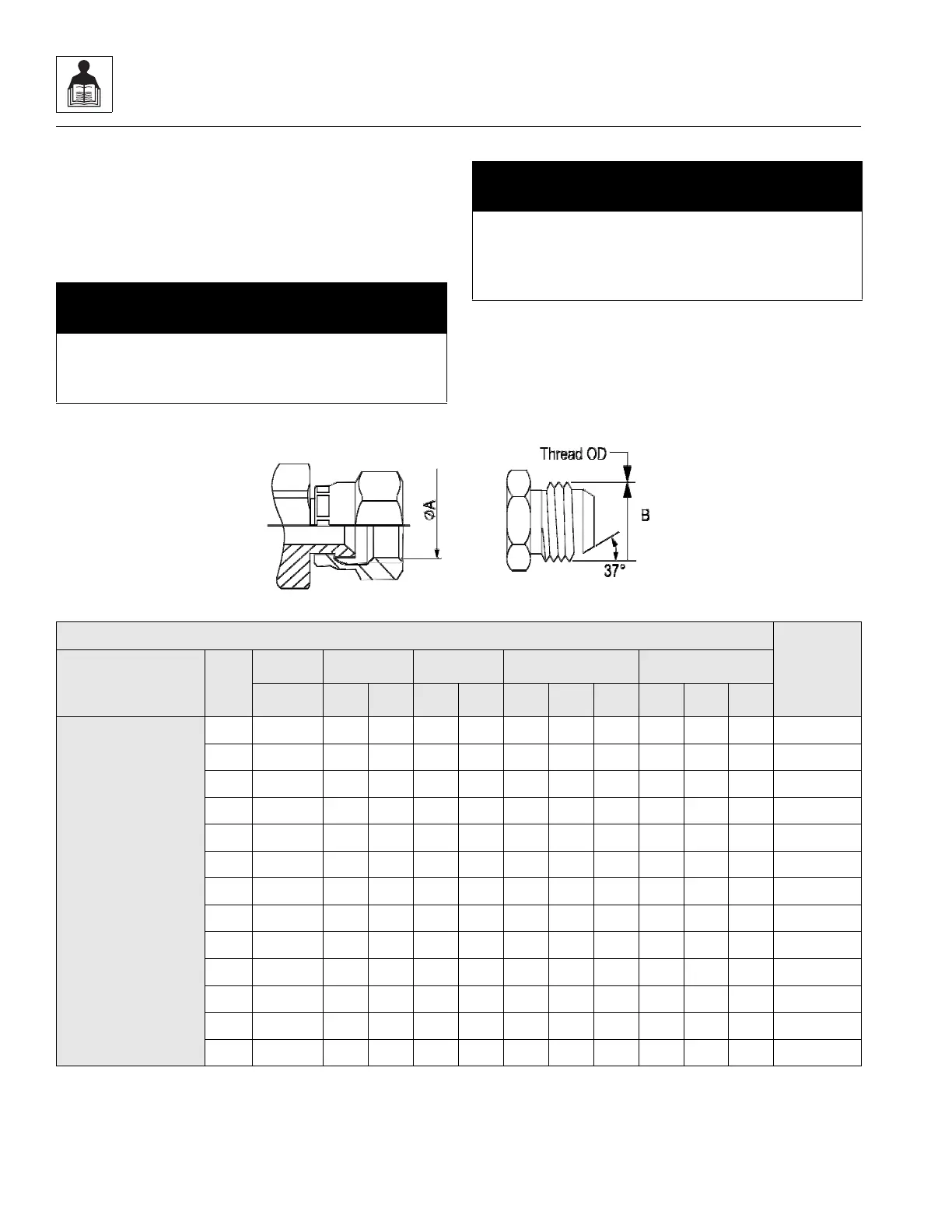
2.9.4 Assembly Instructions for 37° (JIC) Flare
Fittings
1. Inspect the flare for obvious visual squareness and
concentricity issues with the tube OD. Ensure that
surface is smooth, free of rust, weld and brazing splatter,
splits, dirt, foreign matter, or burrs. If necessary, replace
fitting or adapter.
2. Align tube to fitting and start threads by hand.
3. Torque assembly to value listed in below mentioned
table while using the Double Wrench Method.
Note: Torque values provided in below table are segregated
based on the material configuration of the connection.
a. 37° Flare (JIC) Thread - Steel
NOTICE
DO NOT force a misaligned or short hose/tube into
alignment. It puts undesirable strain onto the joint
eventually leading to leakage.
NOTICE
The torque method should NOT be used on lubricated or
oily fittings. No lubrication or sealant is required. The
lubrication would cause increased clamping force and
cause fitting damage.
TYPE/FITTING IDENTIFICATION
Flats From
Wrench
Resistance
(F.F.W.R)**
Material
Dash
Size
Thread
Size
ØA* ØB* [Ft-Lb] [Nm]
(UNF) (in) (mm) (in) (mm) Min Nom Max Min Nom Max
STEEL FITTINGS
WITH STEEL
MATING
COMPONENTS;
UN-LUBRICATED
THREADS
25/16-240.287.000.317.756778910 --
3 3/8-24 0.34 8.60 0.37 9.50 8 9 10 11 12 14 --
4 7/16-20 0.39 10.00 0.44 11.10 13 14 14 18 19 19 1-1/2 to 1-3/4
5 1/2-20 0.46 11.60 0.50 12.70 14 15 15 19 20 21 1 to 1-1/2
6 9/16-18 0.51 13.00 0.56 14.30 22 23 24 30 31 33 1 to 1-1/2
8 3/4-16 0.69 17.60 0.75 19.10 42 44 46 57 60 63 1-1/2 to 1-3/4
10 7/8-14 0.81 20.50 0.87 22.20 60 63 66 81 85 89 1 to 1-1/2
12 1 1/16-12 0.97 24.60 1.06 27.00 84 88 92 114 120 125 1 to 1-1/2
14 1 3/16-12 1.11 28.30 1.19 30.10 100 105 110 136 142 149 1 to 1-1/2
16 1 5/16-12 1.23 31.30 1.31 33.30 118 124 130 160 168 176 3/4 to 1
20 1 5/8-12 1.54 39.20 1.63 41.30 168 176 185 228 239 251 3/4 to 1
24 1 7/8-12 1.80 45.60 1.87 47.60 195 205 215 264 278 291 3/4 to 1
32 2 1/2-12 2.42 61.50 2.50 63.50 265 278 292 359 377 395 3/4 to 1
NOTE:
* ØA and ØB thread dimensions for reference only.
** Refer to Section 2.9.15, “FFWR and TFFT Methods,” for FFWR procedure requirements.

 Loading...