Cab and Covers
4-7
6036, 6042, 8042, 10042, 10054 31211015
b. Joystick Assembly Installation
1. Secure the joystick to the cab with the previously used
hardware.
2. Connect the tilt function electrical connector.
3. Uncap and connect the previously removed hydraulic
hoses to the joystick.
4. Properly connect the battery. Refer Section 9.8,
“Battery”, for procedure.
5. Test the joystick function:
• Move the joystick handle rearward, activating the boom
lift function. The boom should RISE.
• Move the joystick handle forward, activating the boom
lower function. The boom should LOWER.
• Move the joystick handle to the right, activating the
boom extend function. The boom should EXTEND.
• Move the joystick handle to the left, activating the
boom retract function. The boom should RETRACT.
• Move the joystick switch rearward, activating the
attachment tilt function. The boom should TILT UP.
• Move joystick switch forward, activating attachment tilt
function. The boom should TILT DOWN.
6. Install console panel in the cab.
7. Remove the Do Not Operate Tags from both the ignition
key switch and the steering wheel.
4.3.6 Auxiliary/Frame Level Lever Assemblies
These removal and installation instructions apply to the
frame level and auxiliary hydraulic joysticks.
a. Lever Assembly Removal
1. Park the machine on a firm, level surface, level the
machine, fully retract the boom, lower the boom, place
the transmission in (N) NEUTRAL, engage the parking
brake and turn the engine OFF.
2. Place a Do Not Operate Tag on both the ignition key
switch and steering wheel, stating that the machine
should not be operated.
3. Properly disconnect the battery. Refer Section 9.8,
“Battery”, for procedure.
4. Remove the console panel in the cab.
Note: Record the location, and label all cables to ensure correct
installation.
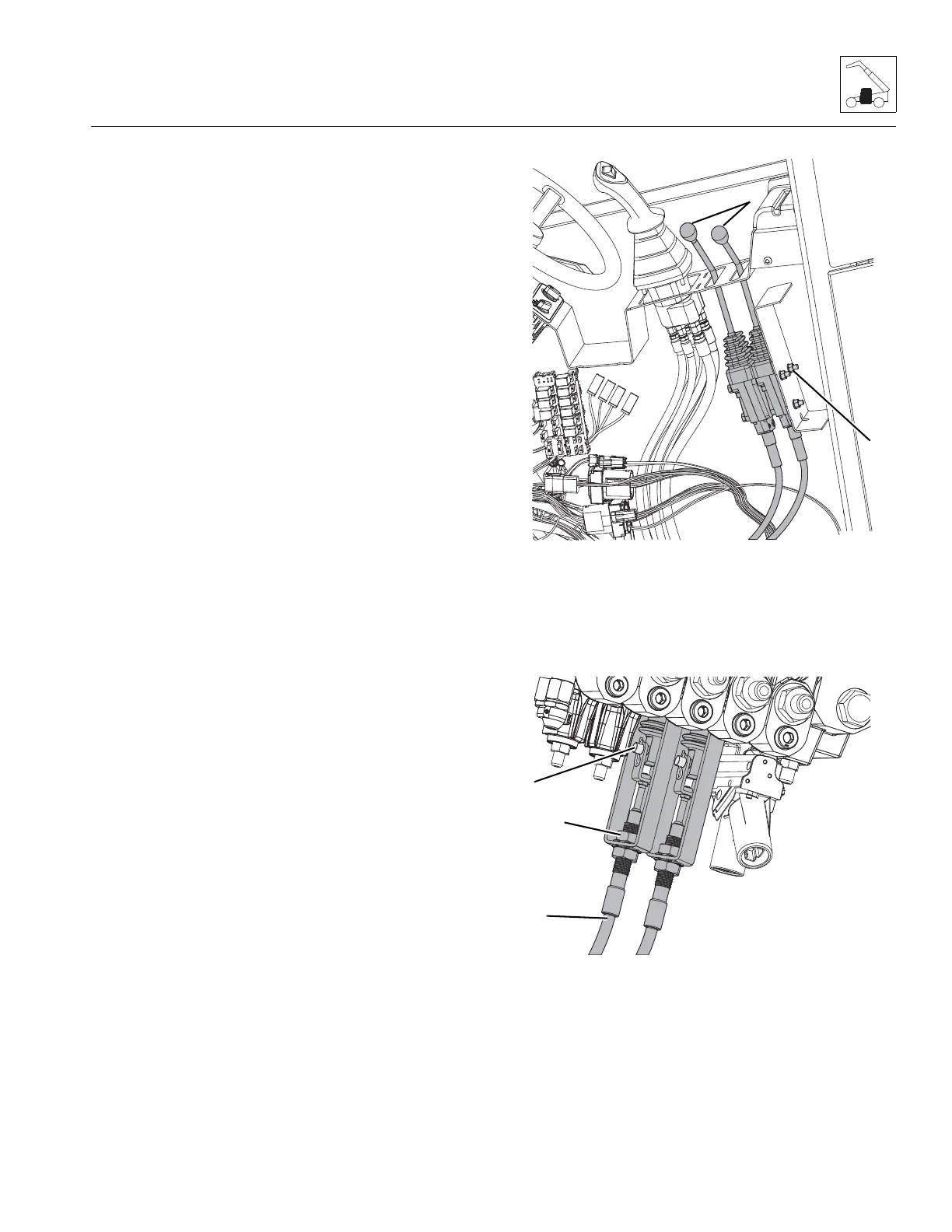
5. Remove the knob on each control lever (18).
6. Loosen and remove the three bolts (19) securing the
control levers.
7. Remove the clip and pin (20) from the main control
valve control spool.
8. Remove the bolts securing each cable bracket (21) to
the main control valve.
 Loading...