Hydraulic Section
8-39
6036, 6042, 8042, 10042, 10054 31211015
8. Wipe up any hydraulic fluid spillage in, on, near and
around the machine and the work area.
8.6.4 Hydraulic Oil Reservoir Replacement
The hydraulic reservoir and the fuel tank are one unit and are
removed together. Refer to Section 7.6.2, “Fuel/Hydraulic Oil
Tank”, for information on hydraulic reservoir/fuel tank
replacement.
8.7 HYDRAULIC SYSTEM PUMP
For internal service instructions contact your local
authorized service distributor.
8.7.1 Pump Replacement
a. Pump Removal
1. Park the machine on a firm, level surface, level the
machine, fully retract the boom, raise the boom, place
the transmission in (N) NEUTRAL, engage the park brake
and shut the engine OFF.
2. Place a Do Not Operate Tag on both the ignition key
switch and the steering wheel, stating that the machine
should not be operated.
3. Properly support the boom.
4. Open the engine cover. Allow the system fluids to cool.
5. Properly disconnect the battery. Refer Section 9.8,
“Battery”, for procedure.
6. Drain the hydraulic reservoir. Refer to Section 8.6.1,
“Hydraulic Oil Reservoir Draining”.
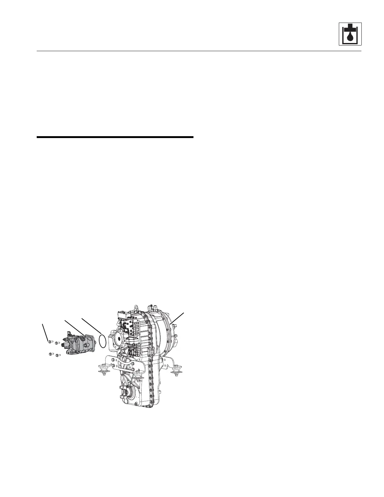
7. Thoroughly clean the pump (1) and surrounding area.
8. Label, disconnect and cap the hydraulic hoses attached
to the pump.
9. Remove the bolts (2), lockwashers and washers
securing the pump to the transmission (3).
10. Remove the o-ring (4) located between the
transmission and the pump. Wipe up any hydraulic oil
spillage.
11. Remove the hydraulic fittings from the pump to use for
later installation.
Note: Before removing any fittings from the pump, note their
orientation to ensure correct installation.
Note: DO NOT disassemble the operating pump. The pump is
pre-set from the manufacturer. Any adjustments or repairs
performed by anyone other than an authorized dealer could
void the warranty.
b. Pump Installation
1. Install the fittings on the pump in the same orientation
as noted during removal.
2. Place the pump and a new, oiled o-ring into position on
the transmission. Align the pump shaft with the internal
transmission gear, so that the machined teeth mesh
together.
3. Align the bolt holes with the pump mount holes. Secure
the pump to the transmission with the previously used
hardware.
4. Uncap and connect the previously labeled hydraulic hoses
to their appropriate locations.
5. Fill the hydraulic reservoir. Refer to Section 8.6.2,
“Hydraulic Oil Reservoir Filling”.
6. Prime the pump by filling the case drain port with fresh,
filtered hydraulic oil from a clean container before
installing the case drain connector and hose.
7. Check all routing of hoses and tubing for sharp bends or
interference with any rotating members. All tube and
hose clamps must be tight.
8. Properly connect the battery. Refer Section 9.8,
“Battery”, for procedure.
9. Remove boom support.
10. Remove the Do Not Operate Tags from both the ignition
key switch and the steering wheel.
11. Close and secure the engine cover.
12. Start engine and run at approximately one-third to one-
half throttle for about one minute without moving the
machine or operating any hydraulic functions.
13. Inspect for leaks and check all fluid levels. The hydraulic
reservoir oil level must be to the middle of the sight
gauge.