SNR S2940-8G-v2 Switch Configuration Guide
Multi-to-One VLAN Translation Configuration
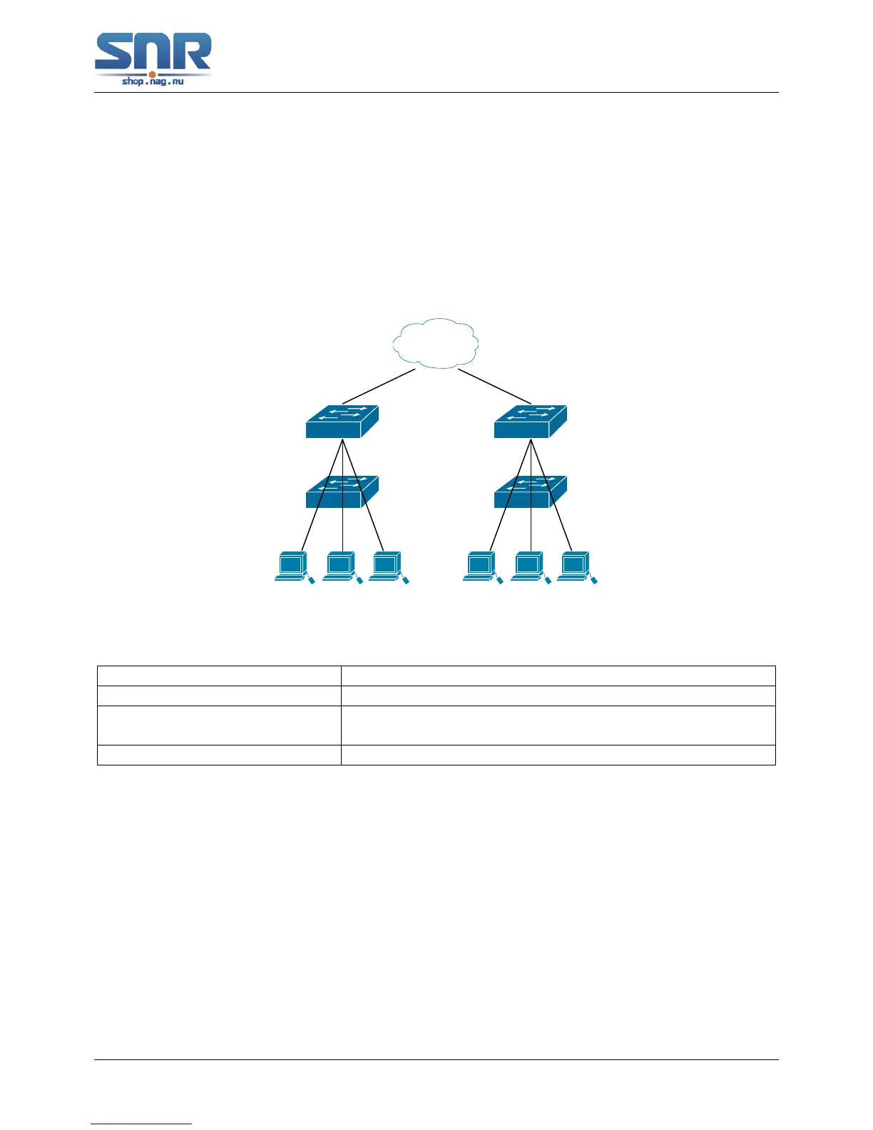
20.3 Typical application of Multi-to-One VLAN Translation
Scenario:
UserA, userB and userC belong to VLAN1, VLAN2, VLAN3 respectively. Before entering the
network layer, data traffic of userA, userB and userC is translated into VLAN 100 by Ethernet1/0/1
of edge switch1. Contrarily, data traffic of userA, userB and userC will be translated into VLAN1,
VLAN2, VLAN3 by Ethernet1/0/1 of edge switch1 from network layer respectively. In the same
way, it implements multi-to-one translation for userD, userE and userF on Ethernet1/0/1 of edge
switch2.
UserD
VID=1
UserF
VID=3
UserE
VID=2
UserA
VID=1
UserB
VID=3
UserB
VID=2
User A,B,C VID=100 User D,E,F VID=200
Figure 20.1: VLAN-translation typical application
Configuration Item Configuration Explanation
VLAN Switch1, Switch2
Trunk Port Downlink port 1/0/1 and uplink port 1/0/5 of Switch1 and
Switch 2
Multi-to-One VLAN-translation Downlink port 1/0/1 of Switch1 and Switch2
Configuration procedure is as follows:
Switch1, Switch2:
switch(Config)#vlan 1-3;100
switch(Config-Ethernet1/0/1)#switchport mode trunk
switch(Config-Ethernet1/0/1)#vlan-translation n-to-1 1-3 to 100
switch(Config)#interface ethernet 1/0/5
switch(Config-Ethernet1/0/5)#switchport mode trunk
switch(Config-Ethernet1/0/5)#exit
20.4 Multi-to-One VLAN Translation Troubleshooting
• Can not be used with Dot1q-tunnel and VLAN-Translation at the same time.
141
 Loading...