SNR S2940-8G-v2 Switch Configuration Guide
sFlow Configuration
8. Configure the analyzer used by sFlow
Command Explanation
Global Mode
sflow analyzer sflowtrend
no sflow analyzer sflowtrend
Configure the analyzer used by sFlow, the no command
deletes the analyzer.
62.3 sFlow Examples
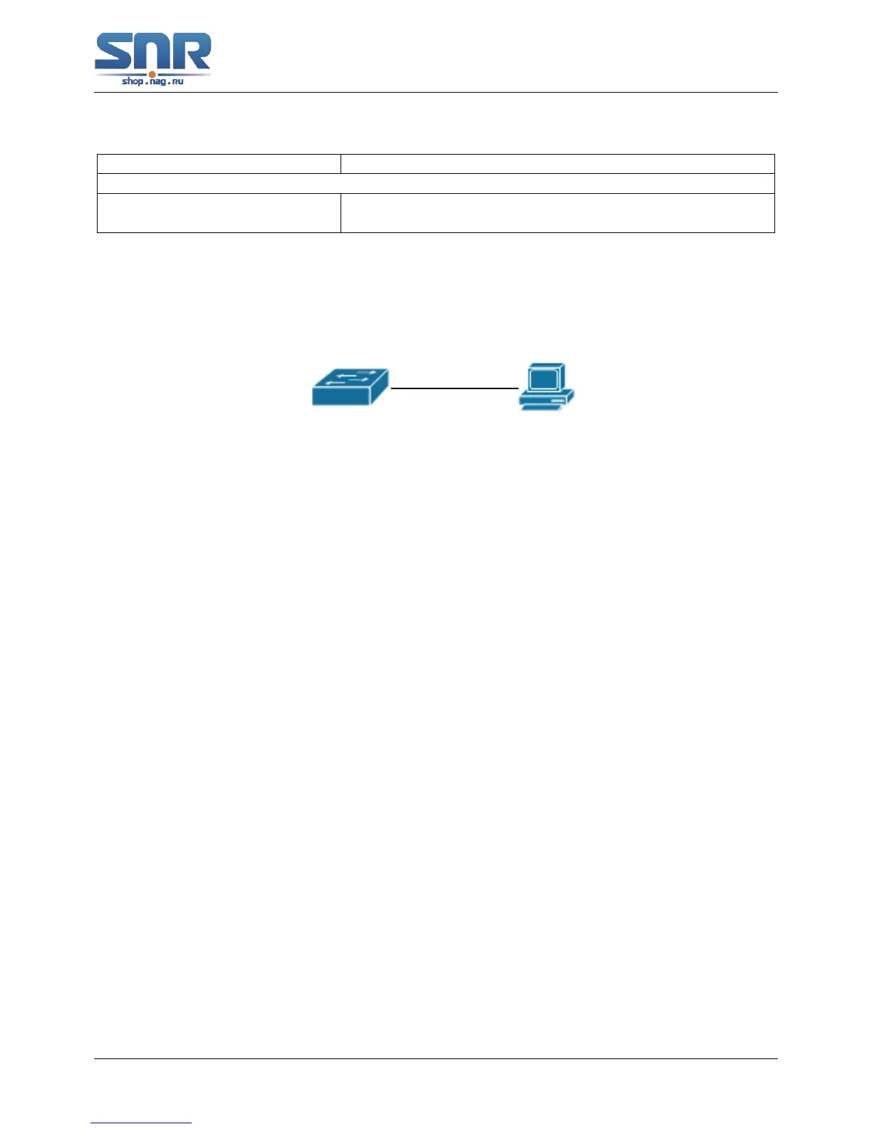
Figure 62.1: sFlow configuration topology
As shown in the figure, sFlow sampling is enabled on the port 1/1 and 1/2 of the switch. Assume
the sFlow analysis software is installed on the PC with the address of 192.168.1.200. The address
of the layer 3 interface on the SwitchA connected with PC is 192.168.1.100. A loopback interface
with the address of 10.1.144.2 is configured on the SwitchA. sFlow configuration is as follows:
Configuration procedure is as follows:
Switch#config
Switch(config)#sflow agent-address 10.1.144.2
Switch(config)#sflow destination 192.168.1.200
Switch(config)#sflow priority 1
Switch(config)#interface ethernet1/1
Switch(Config-If-Ethernet1/1)#sflow rate input 10000
Switch(Config-If-Ethernet1/1)#sflow rate output 10000
Switch(Config-If-Ethernet1/1)#sflow counter-interval 20
Switch(Config-If-Ethernet1/1)#exit
Switch(config)#interface ethernet1/2
Switch(Config-If-Ethernet1/2)#sflow rate input 20000
Switch(Config-If-Ethernet1/2)#sflow rate output 20000
Switch(Config-If-Ethernet1/2)#sflow counter-interval 40
401
 Loading...