SNR S2940-8G-v2 Switch Configuration Guide
Port Isolation Function Configuration
3. Display the configuration of port isolation
Command Explanation
Admin Mode and Global Mode
show isolate-port group [
<WORD> ]
Display the configuration of port isolation, including all con-
figured port isolation groups and Ethernet ports in each
group.
4.3 Port Isolation Function Typical Examples
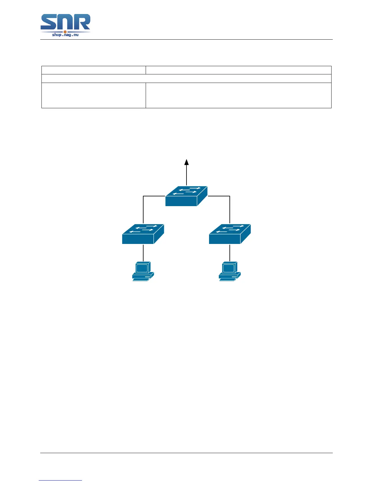
Figure 4.1: Typical example of port isolation function
The topology and configuration of switches are showed in the figure above, with e1/1, e1/10
and e1/15 all belonging to VLAN 100. The requirement is that, after port isolation is enabled
on switch S1, e1/1 and e1/10 on switch S1 can not communicate with each other, while both of
them can communicate with the uplink port e1/15. That is, the communication between any pair
of downlink ports is disabled while that between any downlink port and a specified uplink port is
normal. The uplink port can communicate with any port normally. The configuration of S1:
Switch(config)#isolate-port group test
Switch(config)#isolate-port group test switchport interface ethernet 1/1;1/10
53
 Loading...