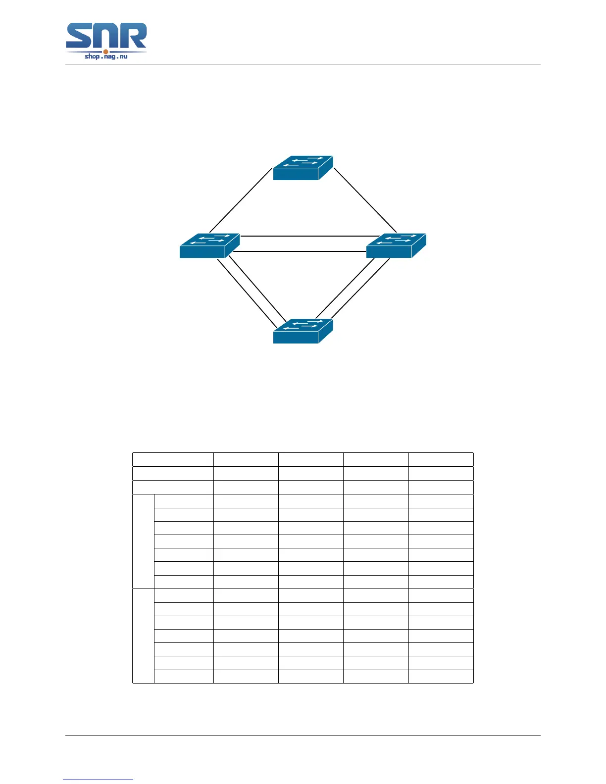
Figure 25.2: Typical MSTP Application Scenario
The connections among the switches are shown in the above figure. All the switches run in the
MSTP mode by default, their bridge priority, port priority and port route cost are all in the default
values (equal). The default configuration for switches is listed below:
Bridge Name SW1 SW2 SW3 SW4
Bridge MAC ...00-00-01 ...00-00-02 ...00-00-03 ...00-00-04
Bridge Priority 32768 32768 32768 32768
Port Priority
port 1 128 128 128
port 2 128 128 128
port 3 128 128
port 4 128 128
port 5 128 128
port 6 128 128
port 7 128 128
Route Cost
port 1 200000 200000 200000
port 2 200000 200000 200000
port 3 200000 200000
port 4 200000 200000
port 5 200000 200000
port 6 200000 200000
port 7 200000 200000
By default, the MSTP establishes a tree topology (in blue lines) rooted with SwitchA. The ports
marked with 'X' are in the discarding status, and the other ports are in the forwarding status.
171
 Loading...