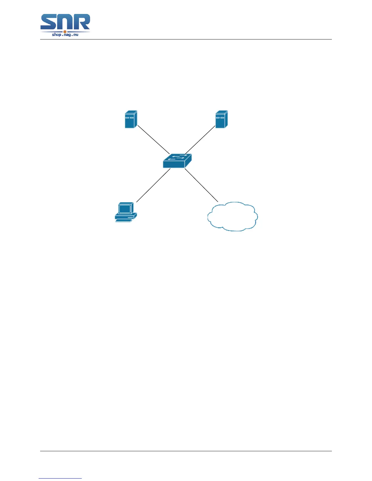
Figure 45.13: The Network Topology of Guest VLAN
Notes: in the figures in this session, E2 means Ethernet 1/0/2, E3 means Ethernet 1/0/3 and
E6 means Ethernet 1/0/6.
As showed in the next figure, a switch accesses the network using 802.1x authentication, with
a RADIUS server as its authentication server. Ethernet1/0/2, the port through which the user ac-
cesses the switch belongs to VLAN100; the authentication server is in VLAN2; Update Server, be-
ing in VLAN10, is for the user to download and update supplicant system software; Ethernet1/0/6,
the port used by the switch to access the Internet is in VLAN5.
As illustrated in the up figure, on the switch port Ethernet1/0/2, the 802.1x feature is enabled,
and the VLAN10 is set as the port's Guest VLAN. Before the user gets authenticated or when
the user fails to do so, port Ethernet1/0/2 is added into VLAN10, allowing the user to access the
Update Server.
As illustrated in the up figure, when the users become online after a successful authentication,
the authentication server will assign VLAN5, which makes the user and Ethernet1/0/6 both in
VLAN5, allowing the user to access the Internet.
The following are configuration steps:
# Configure RADIUS server.
Switch(config)#radius-server authentication host 10.1.1.3
Switch(config)#radius-server accounting host 10.1.1.3
Switch(config)#radius-server key test
Switch(config)#aaa enable
Switch(config)#aaa-accounting enable
319
 Loading...