SNR S2940-8G-v2 Switch Configuration Guide
LLDP Function Operation Configuration
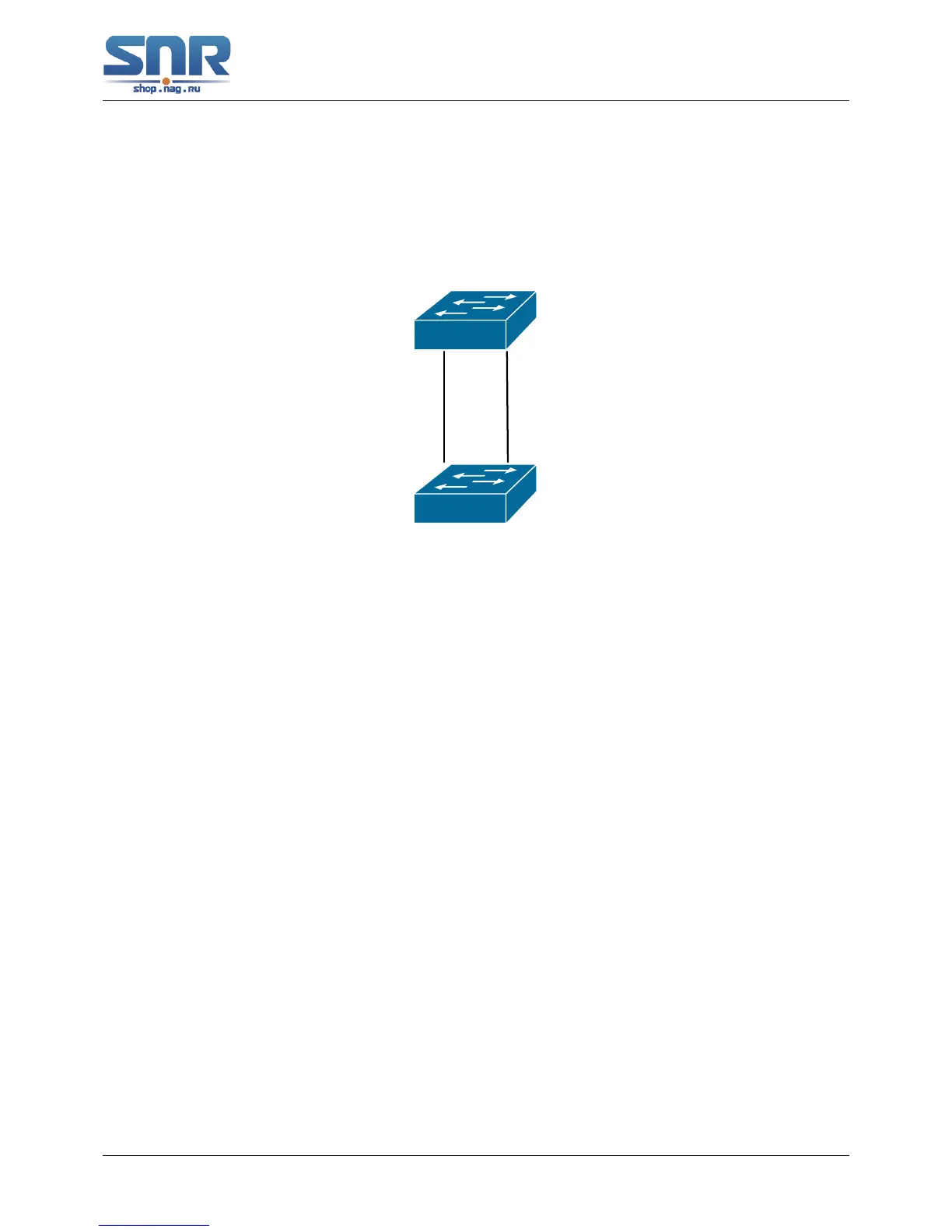
7.3 LLDP Function Typical Example
In the network topology graph above, the port 1,3 of SWITCH B are connected to port 2,4 of
SWITCH A. Port 1 of SWITCH B is configured to message-receiving-only mode, Option TLV of
port 4 of SWITCH A is configured as portDes and SysCap.
Figure 7.1: LLDP Function Typical Configuration Example
SWITCH A configuration task sequence:
SwitchA(config)# lldp enable
SwitchA(config)#interface ethernet 1/4
SwitchA(Config-If-Ethernet1/4)#lldp transmit optional tlv portDesc sysCap
SwitchA(Config-If-Ethernet1/4)exit
SWITCH B configuration task sequence:
SwitchB(config)#lldp enable
SwitchB(config)#interface ethernet1/1
SwitchB(Config-If-Ethernet1/1)#lldp mode receive
SwitchB(Config-If-Ethernet1/1)#exit
7.4 LLDP Function Troubleshooting
• LLDP function is disabled by default. After enabling the global switch of LLDP, users can
enable the debug switch debug lldp simultaneously to check debug information.
• Using show function of LLDP function can display the configuration information in global or
port configuration mode.
68
 Loading...