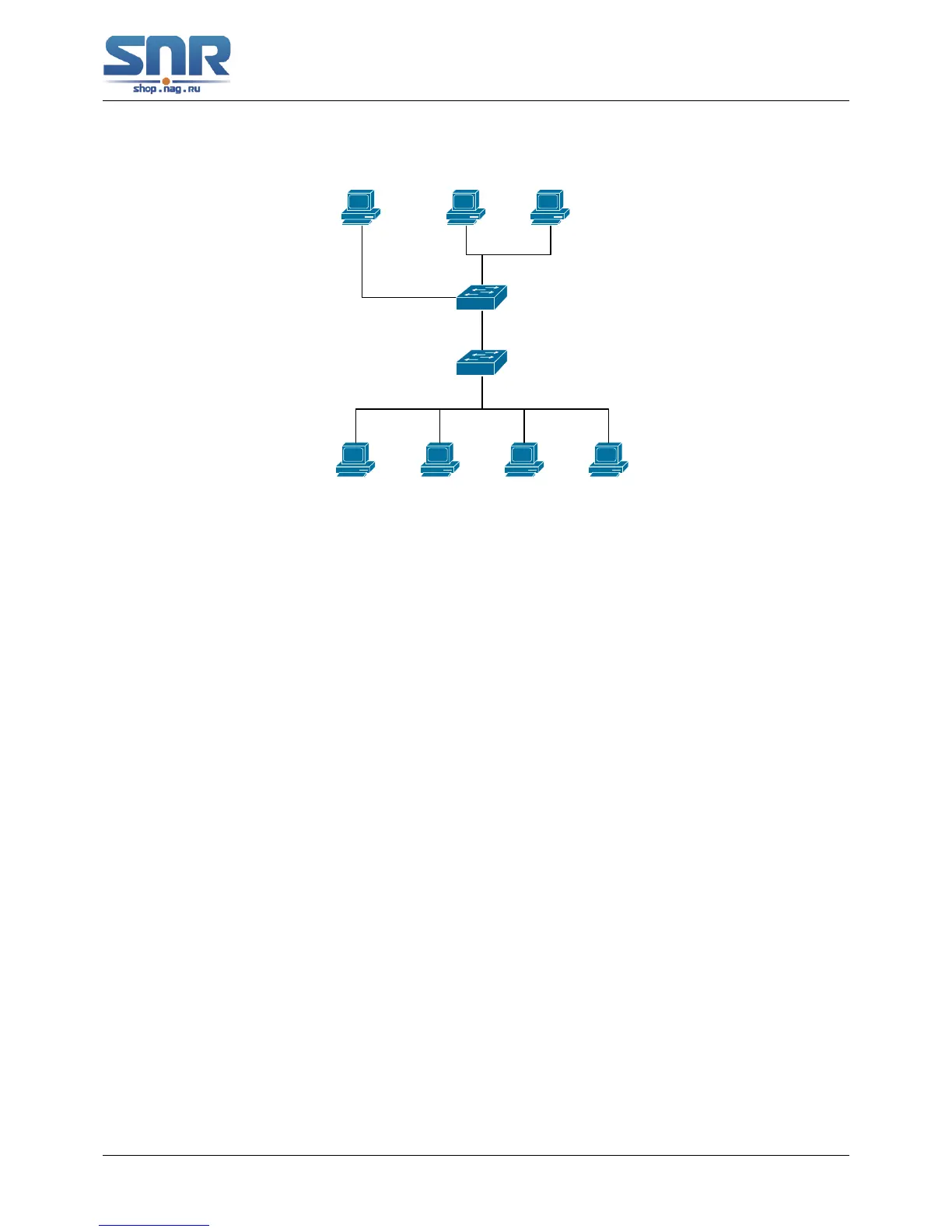
Figure 40.2: The switches as IGMP Queries
The configuration of Switch2 is the same as the switch in scenario 1, SwitchA takes the place
of Multicast Router in scenario 1. Let's assume VLAN 60 is configured in SwitchA, including ports
1, 2, 10 and 12. Port 1 connects to the multicast server, and port 2 connects to Switch2. In order
to send Query at regular interval, IGMP query must enabled in Global mode and in VLAN60.
The configuration steps are listed below:
SwitchA(config)#ip igmp snooping
SwitchA(config)#ip igmp snooping vlan 60
SwitchA(config)#ip igmp snooping vlan 60 L2-general-querier
SwitchB#config
SwitchB(config)#ip igmp snooping
SwitchB(config)#ip igmp snooping vlan 100
SwitchB(config)#ip igmp snooping vlan 100 mrouter interface ethernet 1/0/1
Multicast Configuration
The same as scenario 1
IGMP Snooping listening result:
Similar to scenario 1
Scenario 3: To run in cooperation with layer 3 multicast protocols.
SWITCH which is used in Scenario 1 is replaced with ROUTER with specific configurations
remains the same. And multicast and IGMP snooping configurations are the same with what it is
in Scenario 1. To configure PIM-SM on ROUTER, and enable PIM-SM on vlan 100 (use the same
PIM mode with the connected multicast router)
Configurations are listed as below:
switch(config)#ip pim multicast-routing
switch(config)#interface vlan 100
switch(config-if-vlan100)#ip pim sparse-mode
268
 Loading...