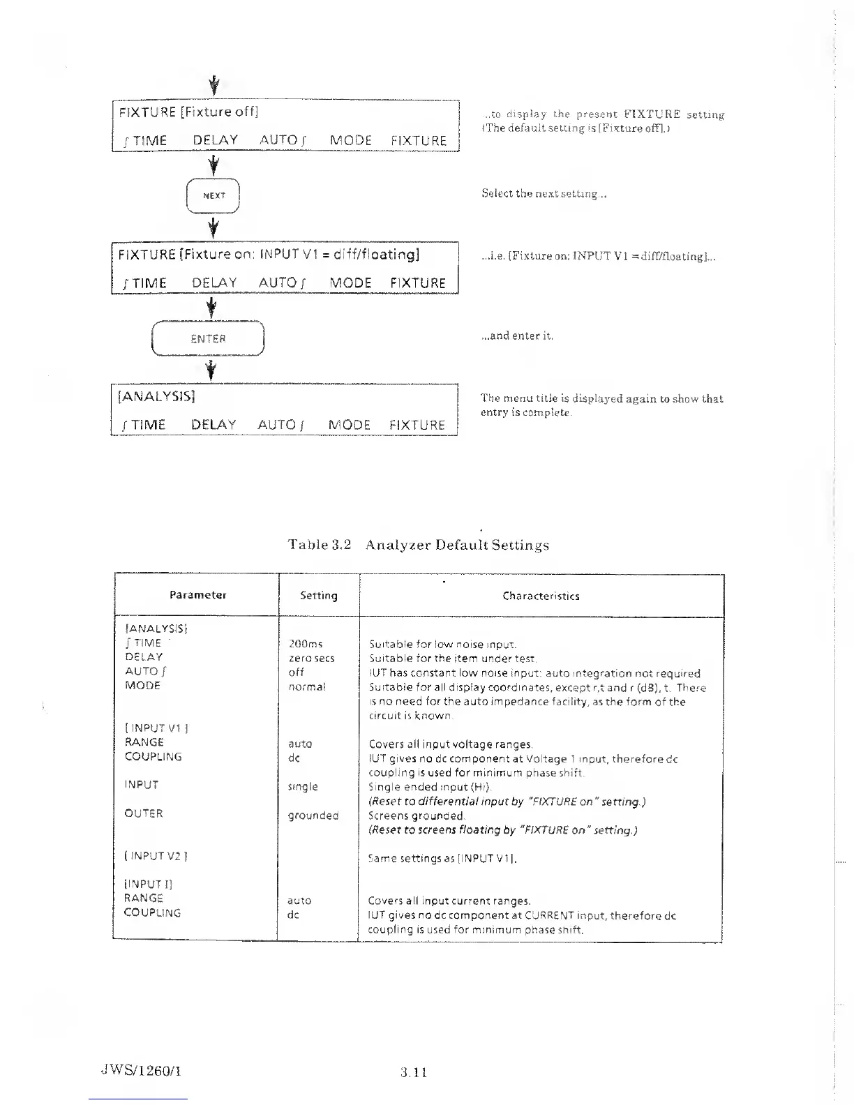
...to
display the present
FIXTURE setting
(The default setting is (Fixture
off].)
t
Select the next setting...
...i.e. (Fixture on: INPUT
VI
=
diff/floatingj...
...and enter it.
The menu
title is displayed again
to show that
entry
is complete.
Table
3.2 Analyzer
Default Settings
Parameter
Setting
Characteristics
[ANALYSIS!
/
TIME
200ms Suitable for low
noise input.
DELAY
zero secs Suitable for the
item under test.
AUTO
/
off
IUT has constant low noise input:
auto integration not required
MODE
(
INPUT VI
|
normal Suitable for all
display coordinates,
except
r,t and r
(dB),
t.
There
is no need for
the auto impedance facility,
as the form of the
circuit is known.
RANGE
auto Covers all
input voltage ranges.
COUPLING
dc IUT gives no
dc
component
at Voltage 1 input, therefore
dc
coupling is
used
for minimum
phase
shift.
INPUT
single Single
ended
input
(Hi).
(Reset
to
differential
input by "FIXTURE on
"
setting.)
OUTER
grounded
Screens grounded.
(Reset to screens floating
by
"FIXTURE
on
"
setting.)
[
INPUT
V2
}
Same settings as (INPUT VI],
(INPUT
I]
RANGE
auto Covers ail input current ranges.
COUPLING
dc
IUT gives no
dc component at CURRENT input,
therefore
dc
coupling is
used
for minimum
phase shift.
JWS/1
260/1
3.11