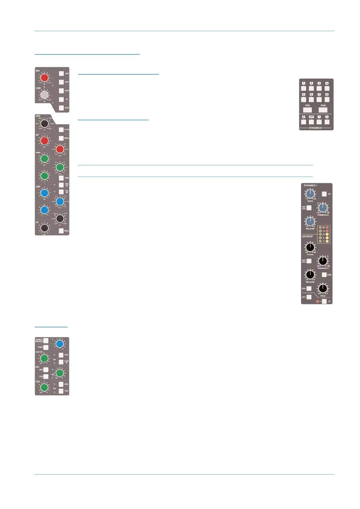
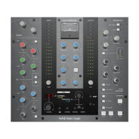
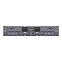
916-924 CHANNEL STRIP
IN
PUT CONFIGURATION
Select the Mic or Line input by pressing FLIP and adjust the input gain using the
a
ppropriate gain pot. The signal level is shown in the meter bridge above the channel.
SI
GNAL
PR
OCESSING
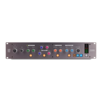
DYNAMICS
Any channel can make use of the two compressor/gate modules housed within the
AWS centre section. Press the 1 or 2 button at the bottom of the meter bridge to
insert one of them into the channel path.
Dynamics cannot be assigned if they are already being used by another channel.
The IN button at the bottom of the compressor/gate module switches it into circuit.
FILTER AND EQ
The filter and EQ are both switched in using the EQ IN switch. Turn the HPF pot
up from minimum to activate the filter – the EQ IN goes from red to green to indicate
that the filter is active.
The EQ has four bands, each with a gain control pot labelled ‘dB’ and frequency
control, and the mid bands have Q control. Press the HF and LF bands’ BELL buttons
to switch from shelf to bell shape.
INSERT POINT
To switch the channel insert into circuit, press the INS IN switch in the centre of the EQ section. Press
PRE to place it before the EQ in the processing chain.
ROUTING
CUE, FX AND EFX SENDS
To activate the Cue or FX sends, press on its gain pot and turn up the gain. The Stereo Cue signal is
normally sourced pre-fader – to move it to after the fader, press POST. The stereo cue also has a pan
control.
There are two stereo cue busses and four FX busses. Each channel can feed one of the stereo cue busses
and two of the FX busses (FX1 or 3, FX2 or 4). Any send can instead control the EFX system, which
uses auxiliary sends to control the level of the channel’s feed to the track busses or direct output – use
the CUE B, FX3, FX4 and EFX switches to select between sends.
AWS 916-924 Tutorial
AWS δelta Owner’s Manual Page 2a-3