5-5
1-1-2. Preparations
Note1: For details of how remove the cabinet and boards, refer to “2.
DISASSEMBLY”.
Note2: When performing only the adjustments, the lens block and boards
need not be disassembled.
Note3: CF-077 board, MI-040 board: TR model
CF-1000 block, MI-041 board: TRV model
TR model: CCD-TR618/TR618E/TR718E/TR728E/TR818
TRV model: CCD-TRV49/TRV49E/TRV58/TRV58E/TRV59E/
TRV68/TRV78/TRV78E/TRV88/TRV98/TRV98E
1) Connect the equipment for adjustments according to Fig. 5-1-
4, 5-1-5.
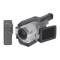
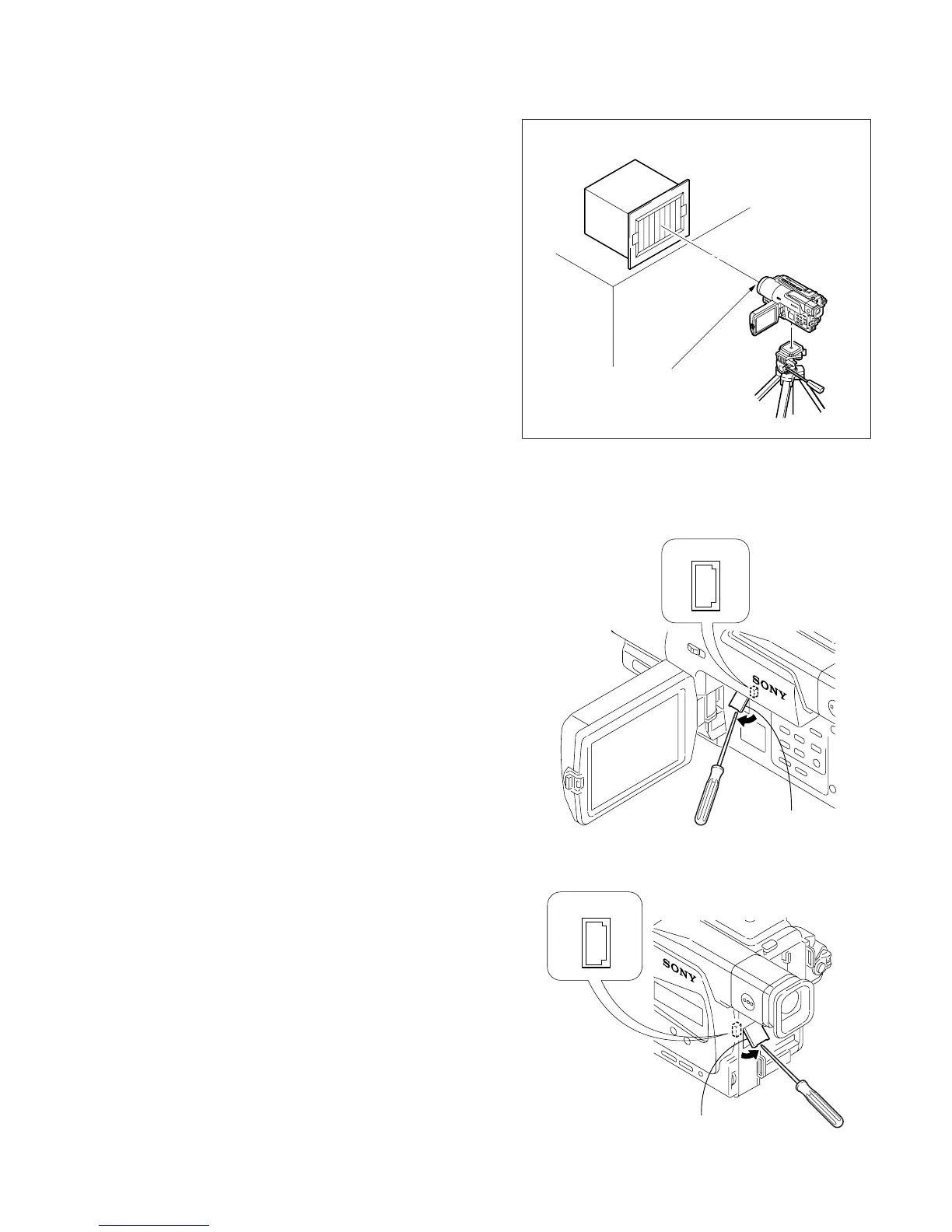
2) Connect the adjustment remote commander to CN713 of VC-
251 board or CPC connector of FP-262 flexible via CPC jig
for BX/BK (J-6082-521-A). To operate the adjustment remote
commander, connect the AC power adapter to the DC IN jack
of CPC jig for BX/BK, or connect the L series Info-LITHIUM
battery to the battery terminal of CPC jig for BX/BK.
(Fig. 5-1-3.)
3) The front panel block (MI-040/041 board, microphone unit,
video light) need not be assembled except during the steady
shot operation check.
Note4: As removing the cabinet (R) (removing the VC-251 board CN709)
means removing the lithium 3V power supply (CF-1000 block/
CF-077 board BT101), data such as date, time, user-set menus
will be lost. After completing adjustments, reset these data. If the
cabinet (R) has been removed, the self-diagnosis data, data on
history of use (total drum rotation time etc.) will be lost. Before
removing, note down the self-diagnosis data (data of page: 2,
address: B0 to C6) and data on history use (data of page: 2, address:
A2 to AA and E0 to E2). (Refer to “5-4. Service Mode” for the
self-diagnosis data and data on the history use.)
Note5: Setting the “Forced Camera Power ON” Mode
1) Select page: 0, address: 01, and set data: 01.
2) Select page: D, address: 10, set data: 01, and press the PAUSE
button.
The above procedure will enable the camera power to be turned
on with the SS-1000 block removed. After completing adjustments,
be sure to exit the “Forced Camera Power ON Mode”.
Note6: Exiting the “Forced Camera Power ON” Mode
1) Select page: 0, address: 01, and set data: 01.
2) Select page: D, address: 10, set data: 00, and press the PAUSE
button.
3) Select page: 0, address: 01, and set data: 00.
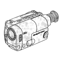
Front of the lens
1.5 m
Pattern box
Fig. 5-1-2.
Fig. 5-1-3.
Remove the
CPC lid
CN713
2
1
2019
Remove the CPC lid
CPC connector
2
1
20
19
[TR model]
[TRV model]
Ver 1.1 2001. 04