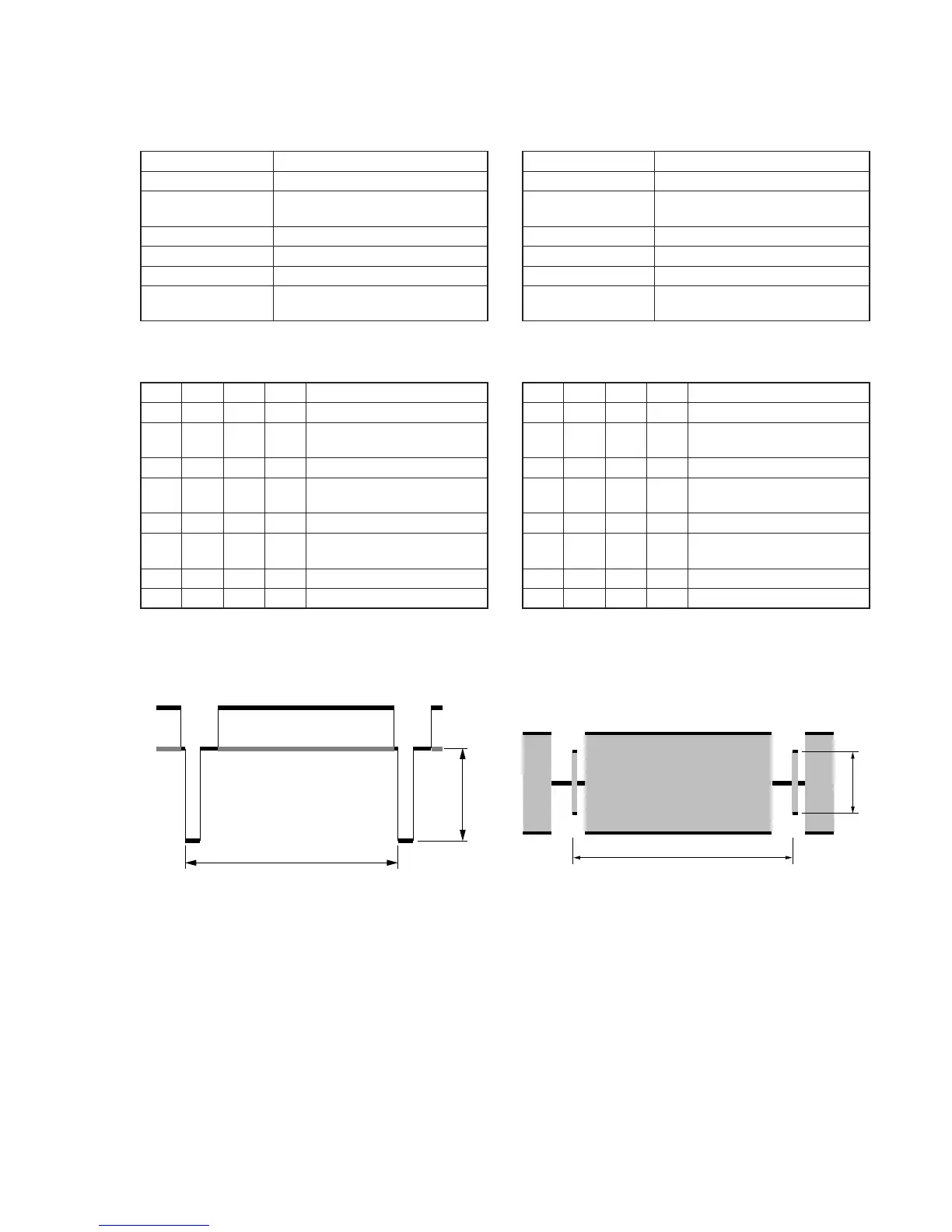
Fig. 5-3-8.
4. Y OUT Level Adjustment (VC-251 board)
Set the Y signal output level. (Adjust the D/A converter out put
level of IC151.)
Mode VTR stop
Signal No signal
Measurement Point Y signal terminal of S VIDEO
terminal (75Ω terminated )
Measuring Instrument Oscilloscope
Adjustment Page F
Adjustment Address 67
Specified Value A=286 ± 5mV (NTSC)
A=300 ± 5mV (PAL)
Note1: Insert a plug into the S video terminal.
Adjusting method:
Order Page
Address
Data Procedure
1 0 01 01 Set the data.
2 2 01 41 Set the data, and press PAUSE
button.
3 6 61 30 Set the data,.
4F67
Change the data and set the SYNC
level (A) to the specified value.
5 F 67 Press PAUSE button.
6 2 01 00 Set the data, and press PAUSE
button.
7 6 61 10 Set the data.
8 0 01 00 Set the data.
5. C OUT Level Adjustment (VC-251 board)
Set the chroma signal output level. (Adjust the D/A converter out
put level of IC151.)
Mode VTR stop
Signal No signal
Measurement Point Chroma signal terminal of S VIDEO
terminal (75Ω terminated )
Measuring Instrument Oscilloscope
Adjustment Page F
Adjustment Address 68
Specified Value A=286 ± 5mV (NTSC)
A=300 ± 5mV (PAL)
Note1: Insert a plug into the S video terminal.
Adjusting method:
Order Page
Address
Data Procedure
1 0 01 01 Set the data.
2 2 01 41 Set the data, and press PAUSE
button.
3 6 61 30 Set the data,.
4 F 68 Change the data and set the burst
level (A) to the specified value.
5 F 68 Press PAUSE button.
6 2 01 00 Set the data, and press PAUSE
button.
7 6 61 10 Set the data,.
8 0 01 00 Set the data.