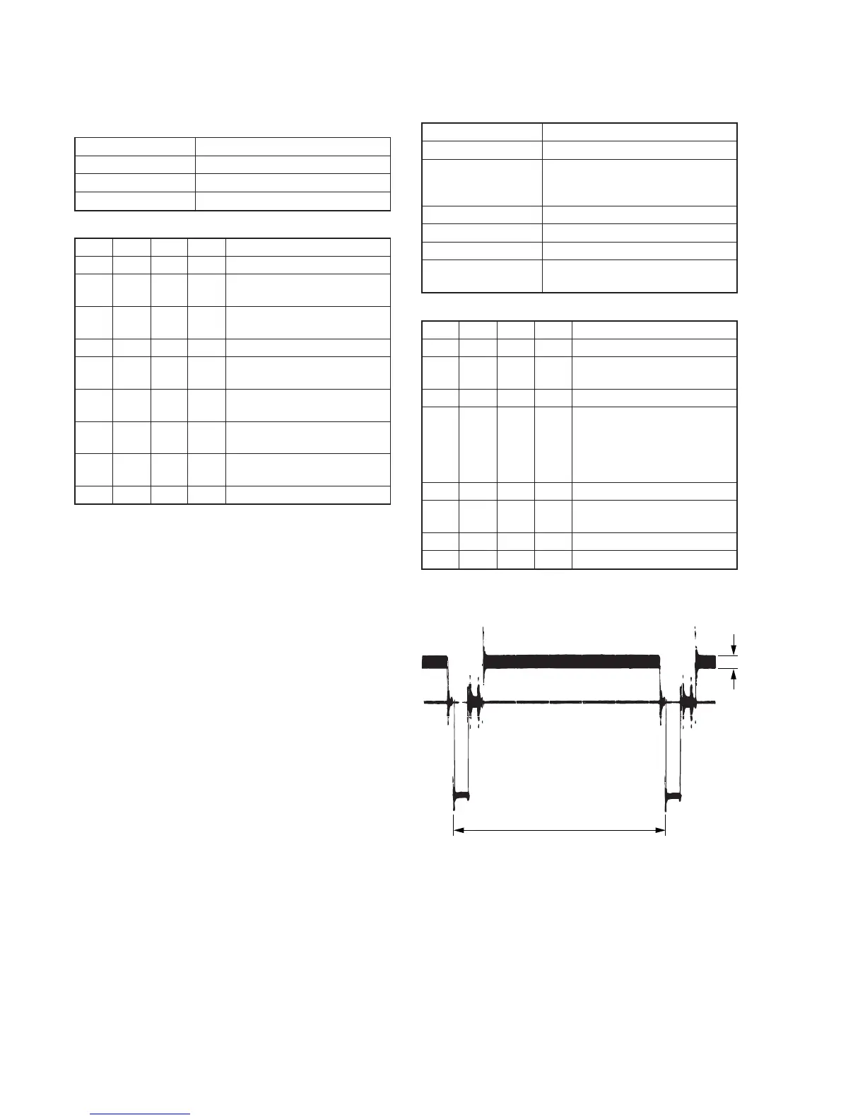
Fig. 5-3-6.
2. AFC fo Adjustment (VC-251 board)
Adjust the pull-in range of the A/D converted clock generator during
playback.
Mode VTR stop
Signal No signal
Adjustment Page F
Adjustment Address 65
Adjusting method:
Order Page
Address
Data Procedure
1 0 01 01 Set the data.
2 F 65 50 Set the data, and press PAUSE
button.
3 2 01 4D Set the data, and press PAUSE
button.
4 Wait for 0.5 sec.
5 6 01 C5 Set the data, and press PAUSE
button.
6 6 02 Check that the data changes to
“01”. (Note)
7 2 01 00 Set the data, and press PAUSE
button.
8 6 01 00 Set the data, and press PAUSE
button.
9 0 01 00 Set the data.
Note: The adjustment data will be automatically input to page: F, address:
65.
3. Filter fo Adjustment (VC-251 board)
Adjust the fo frequency of the IC151 built-in filter.
Mode VTR stop
Signal No signal
Measurement Point IR VIDEO (Pin qf of CN713 or Pin
qf of CPC connector of FP-262
flexible)
Measuring Instrument Oscilloscope
Adjustment Page F
Adjustment Address 66
Specified Value Minimum residual chroma signal
components (A= Bellow 35mV)
Adjusting method:
Order Page
Address
Data Procedure
1 0 01 01 Set the data.
2 2 01 4F Set the data, and press PAUSE
button.
3 2 05 40 Set the data,.
4 F 66 Change the data and minimize
the residual chroma signal
components (A).
(The data should be “70” to
“7F”.)
5 F 66 Press PAUSE button.
6 2 01 00 Set the data, and press PAUSE
button.
7 2 05 00 Set the data,.
8 0 01 00 Set the data.