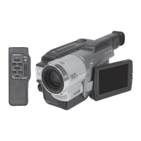
5-25
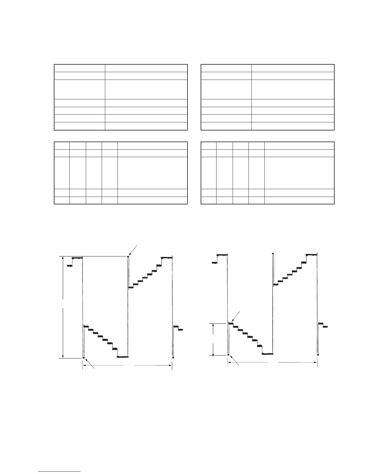
Fig. 5-1-16.Fig. 5-1-15.
Pedestal
Pedestal
A
2H
1. RGB AMP Adjustment (VF-141 board)
Set the D range of the RGB driver used to drive the LCD to the
specified value. If deviated, the LCD screen will become blackish
or saturated (whitish).
Mode Camera
Subject Arbitrary
Measurement Point EVF VG (Pin 7 of CPC connector of
FP-262 flexible or Pin 7 of CN713
of VC-251 board)
Measuring Instrument Oscilloscope
Adjustment Page 7
Adjustment Address D8
Specified Value A = 7.20 ± 0.10V
Adjusting method:
Order Page
Address
Data Procedure
1 0 01 01 Set the data.
2 7 D8 Change the data and set the
voltage (A) between the reversed
waveform pedestal and non-
reversed waveform pedestal to
the specified value.
3 7 D8 Press PAUSE button.
4 0 01 00 Set the data.
2. Contrast Adjustment (VF-141 board)
Set the level of the VIDEO signal for driving the LCD to the specified
value. If deviated, the screen image will be blackish or saturated
(whitish).
Mode Camera
Subject Arbitrary
Measurement Point EVF VG (Pin 7 of CPC connector of
FP-262 flexible or Pin 7 of CN713
of VC-251 board)
Measuring Instrument Oscilloscope
Adjustment Page 7
Adjustment Address DC
Specified Value A=2.20 ± 0.10V
Adjusting method:
Order Page
Address
Data Procedure
1 0 01 01 Set the data.
2 7 DC Change the data and set the
voltage (A) between the 100 IRE
and 0 IRE (pedestal) to the
specified value.
(The data should be “00” to “7F”.)
3 7 DC Press PAUSE button.
4 0 01 00 Set the data.
100 IRE
Pedestal
A
2H