5-24
1-4. COLOR ELECTRONIC VIEWFINDER
SYSTEM ADJUSTMENT
(CCD-TR818)
Note1: The back light (fluorescent tube) is driven by a high voltage AC
power supply. Therefore, do not touch the back light holder to
avoid electrical shock.
Note2: When replacing the LCD unit, be careful to prevent damages
caused by static electricity.
[Adjusting connector]
Most of the measuring points for adjusting the viewfinder system
are concentrated in CN713 of VC-251 board or CPC connector of
FP-262 flexible.
Connect the Measuring instruments and the adjustment remote
commander via the CPC jig for BX/BK (J-6082-521-A) to CN713
or CPC connector. To operate the adjustment remote commander,
connect the AC power adapter to the DC IN jack of CPC jig for BX/
BK, or connect the L series Info-LITHIUM battery to the battery
terminal of CPC jig for BX/BK.
The following table shows the Pin No. and signal name of CN713
or CPC connector.
Table. 5-1-6.
Table. 5-1-7.
The following table shows the arrangement of the test points of
CPC jig for BX/BK. (Pin No. are those of CN713 or CPC connector.)
Pin No.
1
3
5
7
9
11
13
15
17
19
Signal Name
VCO
EVF BL
EVF BL 4.75V
EVF VG
PB RF
REG GND
BPF MONI
REC RF
NC
NC
Pin No.
2
4
6
8
10
12
14
16
18
20
Signal Name
XLANC POWER ON
LANC IN
LANC OUT
CAP FG
REG GND
REG GND
IR VIDEO
RF SWP
NC
NC
Pin No.
3
7
9
13
17
20
16
15
Signal Name
BL
EVF VG
PB RF (MON)
BPF MONI
TMS
TDI
SWP
CAP FG
Pin No.
1
5
10
15
19
18
14
Signal Name
EVF VCO
BL 4.75
GND
REC RF (RF IN)
TDO
TCK
IR VIDEO
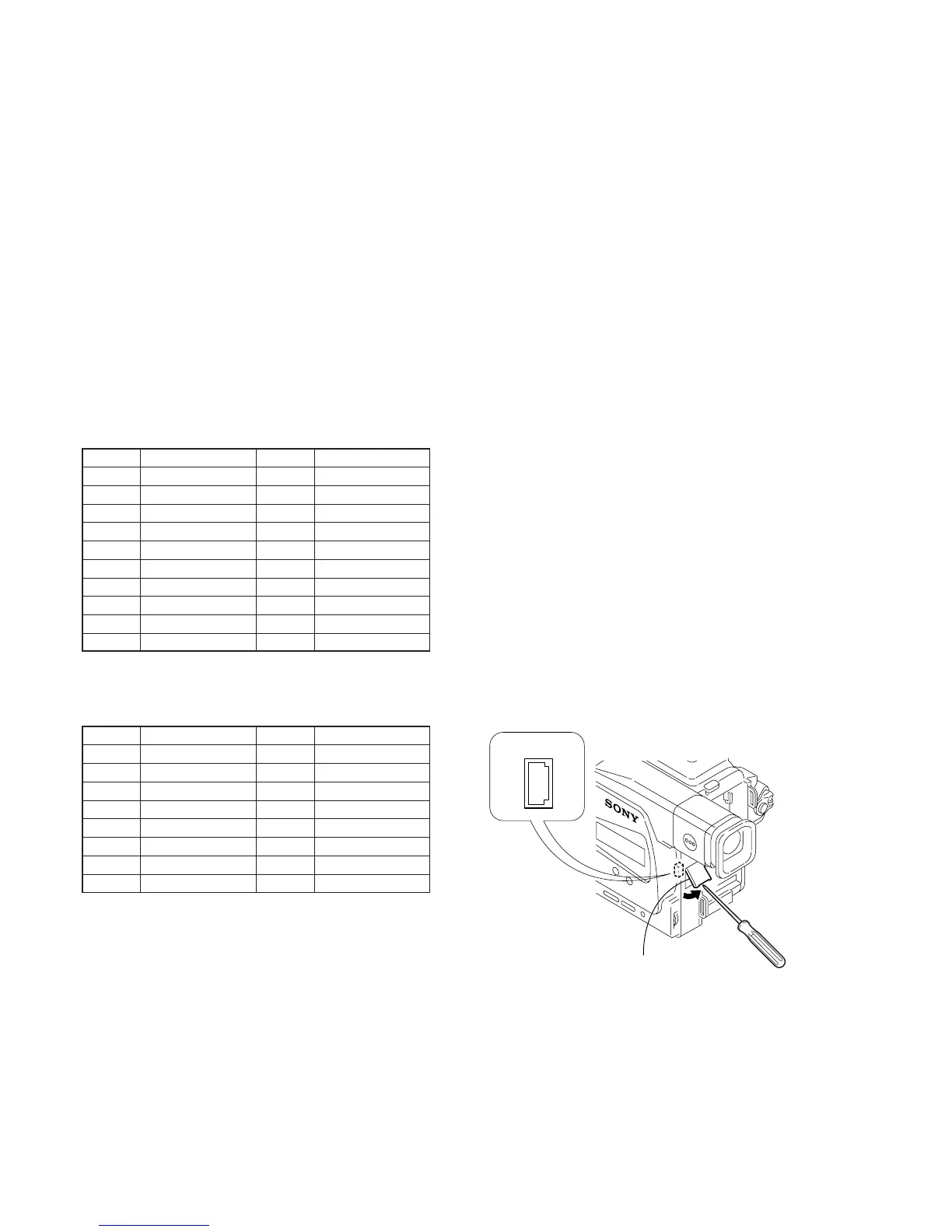
Fig. 5-1-14.
Remove the CPC lid
CPC connector
2
1
20
19