5-44
A
0.18
µ
sec
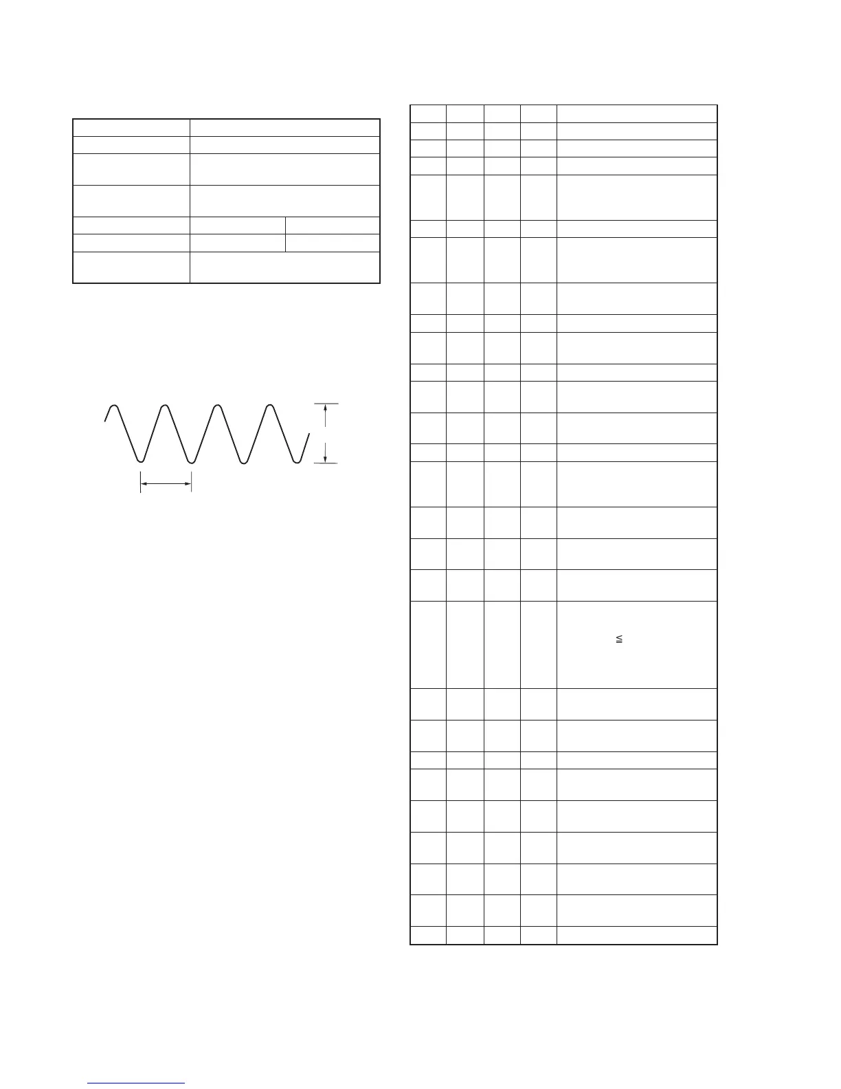
Fig. 5-3-9.
6. REC Y Current Adjustment (VC-251 board)
Adjust the Y FM signal recording current.
Mode VTR recording (SP mode)
Signal No signal
Measurement Point REC RF (Pin qg of CN713 or Pin qg
of CPC connector of FP-262 flexible)
Measuring Instrument Oscilloscope
(20 MHz BW LIMIT: OFF)
Adjustment Page F 7
Adjustment Address 6A, 6B F9
Specified Value A=235 ± 5mV (NTSC)
A=280 ± 5mV (PAL)
Note1: Don’t disconnect the DC power supply of the camcorder during
the following adjustments.
When the following symptom occurs, reset the data of D page to
the values written down.
1) The power is shut off so that unit cannot operate.
Adjusting method:
Order Page
Address
Data Procedure
1 Set to the stop mode.
2 0 01 01 Set the data.
3 D 14 Write down the data.
4 D 14 Set the following data, and press
PAUSE button.
06 (NTSC), 26 (PAL)
5 D 15 Write down the data.
6 D 15 Set the following data, and press
PAUSE button.
6D (NTSC), 6F (PAL)
7 Set to VTR recording mode.
(Note2)
8 E FB Write down the data.
9 E FB 06 Set the data, and press PAUSE
button.
10 F 71 Write down the data.
11 F 71 00 Set the data, and press PAUSE
button.
12 2 01 41 Set the data, and press PAUSE
button.
13 6 63 01 Set the data.
14 F 6B Change the data and set the Y
signal level (A) to the specified
value, and press PAUSE button.
15 F 6B Read the data, and this data is
named D6B.
16 F 6A D6B Set the data, and press PAUSE
button.
17 Convert D6B to decimal notation,
and obtain D6B’. (Note3)
18 Calculate DF9’ using following
equations (Decimal calculation)
When D6B’ 243
DF9’ = D6B’ + 12
When D6B’> 243
DF9’ = 255
19 Convert DF9’ to a hexadecimal
number, and obtain DF9. (Note3)
20 7 F9 DF9 Set the data, and press PAUSE
button.
21 6 63 00 Set the data.
22 2 01 00 Set the data, and press PAUSE
button.
23 F 71 Set the data written down at step
10, and press PAUSE button.
24 E FB Set the data written down at step
8, and press PAUSE button.
25 D 14 Set the data written down at step
3, and press PAUSE button.
26 D 15 Set the data written down at step
5, and press PAUSE button.
27 0 01 00 Set the data.
Note2: Use the REC buttons of the adjustment remote commander (with
the HOLD switch set in the OFF position).
Note3: Refer to “Table 5-4-1. Hexadecimal-decimal Conversion Table”.
Ver 1.1 2001. 04