5-7
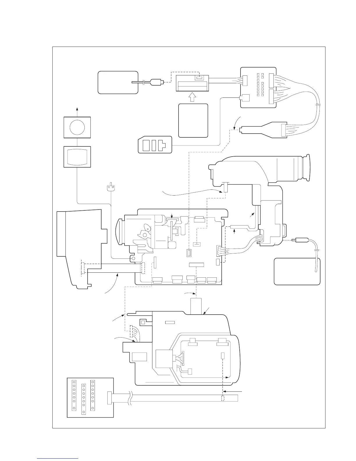
Fig. 5-1-5.
TRV model (CCD-TRV49/TRV49E/TRV58/TRV58E/TRV59E/TRV68/TRV78/TRV78E/TRV88/TRV98/TRV98E)
Note: Use either a AC power adaptor or a Info-LITHIUM battery as the power supply of the CPC jig for BX/BK.
AC power adaptor
(8.4Vdc)
AC-L10
AC-VQ800 etc
Vector scope
Adjustment
remote commander
Color monitor
Terminated at 75
Ω
VIDEO
(Yellew)
AUDIO
(black)
Must be connected when
performing the EVF system
adiustments.
L series
Info LITHIUM
Battery
(7.2Vdc)
LANC
jack
CPC jig for BX/BK (J-6082-521-A)
EVF block
TO SS-1000
block
Must be connected
DC IN
jack
To CF-1000 block CN001
Must be connected when
changing the menu setting
Cabinet (R)
AC power adaptor
(8.4Vdc)
AC-L10
AC-VQ800 etc
MI-041 board
CN754
Lens
block
Must be connected
when performing the
steady shot check.
Must be connected when
performing the LCD system
adjustments.
To PD-131 board
CN5701
Multi CPC jig
(J-6082-311-A)
Must be connected when performing
the LCD system adjustment
PD-131
board
CN5601
CN5501
CN5502
CN5701
CN5702
CN704
CN701
CN101
CN706
CN707
CN712
CN711
CN715
CN713
CN001
VC-251 board
CN703
CN709
CN710
CN291
CN271
A/V OUT
jack
Front
panel
block
Must be connected