VC-251
CF-077
Adjustment remote
commander (RM-95)
Info lithium battery
(L series)
A/V out jack
CPC-jig for BX/BK
(J-6082-521-A)
Monitor TV
Video
Audio
FP-257 flexible board
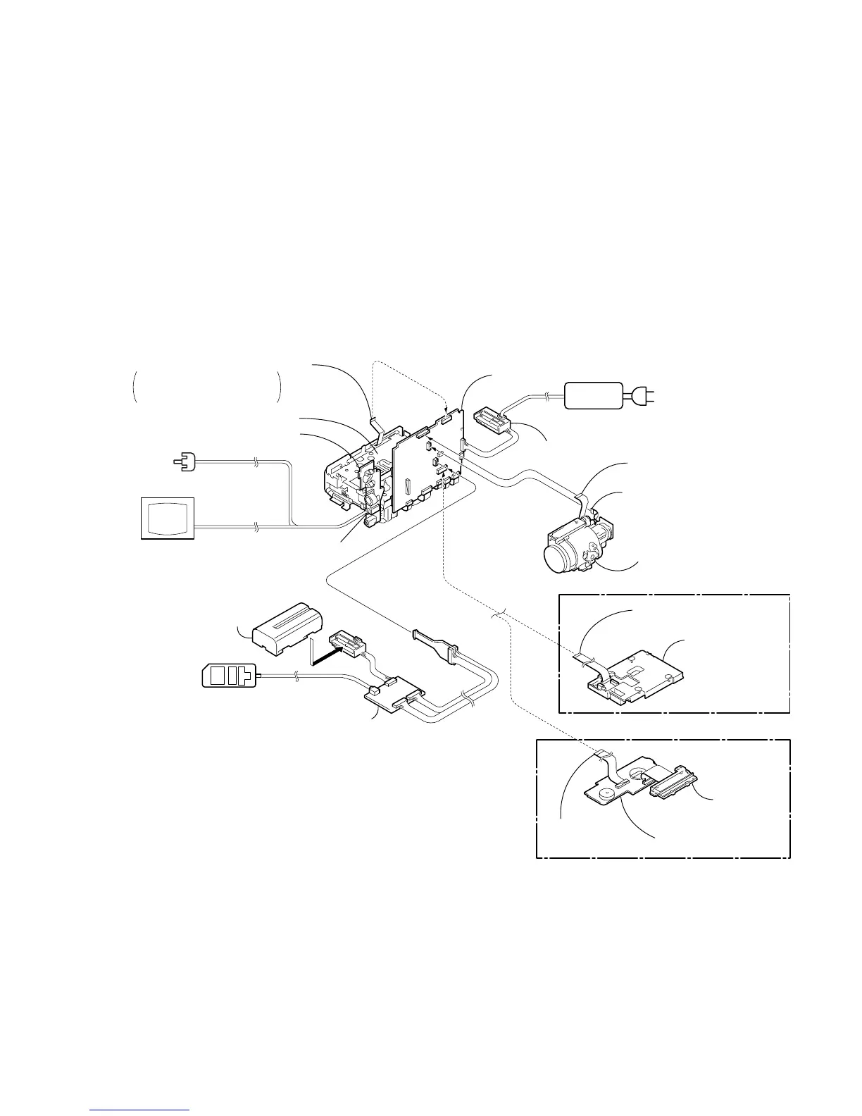
Control switch block (FK-1000) (12P)
When you operate the zoom,
connect the FK-1000 block to
CN710 of VC-251 board.
Mechanism deck
Battery terminal board
[SERVICE POSITION TO CHECK THE CAMERA SECTION]
AC IN
AC power
adaptor
FP-259 flexible board (14P)
Lens block
Flexible board
(from lens block) (24P)
VC-251 board
CF-077 board
FFC-295 flexible
flat cable (24P)
Control switch block
(CF-1000)
FFC-295 flexible
flat cable (24P)
Liquid crystal
display panel,
LCD holder
(TR model)
(TRV model)
Connection to Check the Camera Section
To check the camera section, set the camera to the "Forced camera power ON" mode.
Setting the “Forced Camera Power ON” mode
1) Select page: 0, address: 01, and set data: 01.
2) Select page: D, address: 10, set data: 01, and press
the PAUSE button of the adjustment remote
commander.
Exiting the “Forced Camera Power ON” mode
1) Select page: 0, address: 01, and set data: 01.
2) Select page: D, address: 10, set data: 00, and press
the PAUSE button of the adjustment remote
commander.
3) Select page: 0, address: 01, and set data: 00.
Note: If the machine malfunctions (the operating mode changes by itself), connect the FK-1000 block,
CF-1000 block/CF-077 board.