5-6
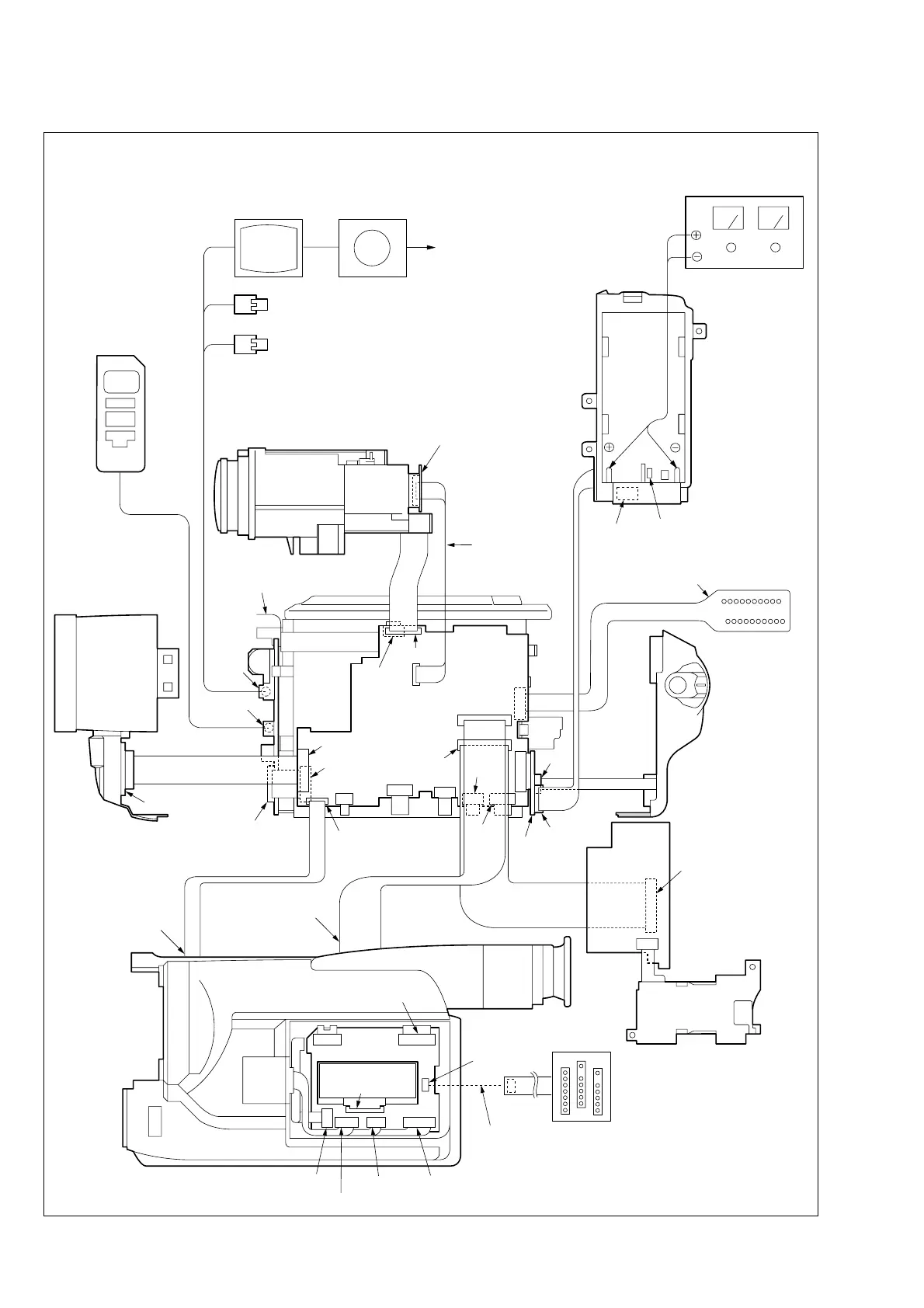
Fig. 5-1-3
2.5 LCD model
Adjustment remote
commander
Video
(yellow)
Color monitor Vector scope
Terminated 75 Ω
Audio L (white)
Audio R (red)
Lens block
CD-242 board
CN101 (720H model)
or
CD-244 board
CN151 (960H model)
Extension cable
(16P, 0.5 mm)
(J-6082-357-A)
CN1551
CN1101
CN1501
CN1108
CN1105
Need not connected
A/V
jack
LANC jack
Front panel block
MI-37 board
CN5804
SE-104 board
CN202
CN1103
CN3101
CN4402
CN4403
CN4404
CN1113
CN253
FU-138
board
CN252
Must be connected when
performing the video system
adjustment.
CPC-13 jig
(J-6082-443-A)
Cabinet (L)
DC IN jack
Battery switch
Battery
terminal
Regulated power
supply (Note 1)
(8.4 ± 0.1 Vdc)
Cabinet (R)
To CF-69 board
CN001
Multi CPC jig
(J-6082-311-A)
Must be connected when performing
the LCD system adjustment.
LCD WINDOW
PD-117 board
CN1111
CN1109
To PD-117 board
CN5701
CN5703
CN5701
CN5704
CN5702
CN5604
CN5501
CN4401
VC-235
board
CN5705
PC-77
board
CN1104
Extension cable
(100P, 0.5 mm)
(J-6082-352-A)
CN802
CN5502
FP-162
FLEXIBLE
CN801
Note 1: Press the battery switch of the battery terminal using adhesive tape, etc.
Note 2: 720H model: DCR-TRV320/TRV320P
960H model: DCR-TRV320E