5-56
3. IR Audio Deviation Adjustment (MI-37 board)
Mode VTR stop
Signal Audio signal:
400 Hz, –7.5 dBs: Audio left and
right terminal of A/V jack
Video signal:
Color bar signal: VIDEO terminal
of A/V jack
Measurement Point AUDIO L terminal and AUDIO R
terminal of IR receiver jig
(Terminated at 47 kΩ)
Measuring Instrument Audio level meter
Adjustment Page F
Adjustment Address 7F
Specified Value Signal level: –7.5 ± 1.0 dBs
Level difference of L and R: Below 2 dB
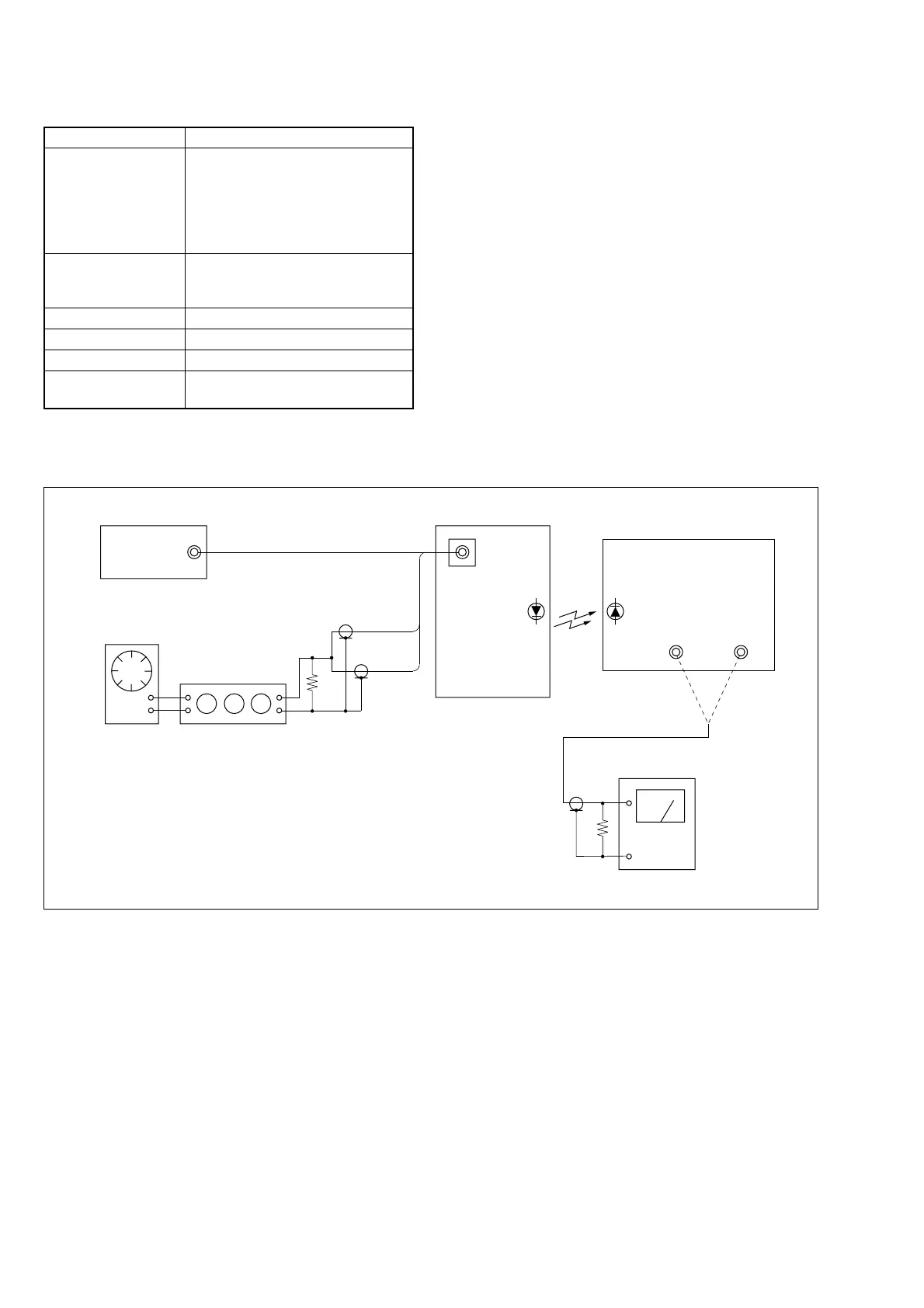
Connection of Equipment
Connect the measuring device as shown in the following figure,
and adjust.
Fig. 5-3-17
Adjusting method:
1) Select page: 0, address: 01, and set data: 01.
2) Connect the audio level meter to the AUDIO L terminal of the
IR receiver jig.
3) Select page: F, address: 7F, change the data and set the 400 Hz
audio signal level to the specified value.
4) Press the PAUSE button.
5) Connect the audio level meter to the AUDIO R terminal of the
IR receiver jig.
6) Check that the 400 Hz audio signal level is within the specified
value. If outside, repeat from step 3).
7) Select page: 0, address: 01, and set data: 00.
(75 Ω)
600 Ω
A/V jack
AUDIO OUT
L
47 kΩ
47 kΩ (1-249-437-11)
600 Ω (270 Ω (1-249-410-11) + 330 Ω (1-249-411-11))
Pattern generator
Video
Audio (L)
Audio (R)
Audio oscillator
Main unit
Attenuator
Audio level meter
VIDEO OUT
R
IR receiver jig



 To Next Page