– 15 –
DCR-TRV320/TRV320E/TRV320P/TRV420E/TRV520/TRV520E/TRV520P/TRV525
TRV620E/TRV720/TRV720E
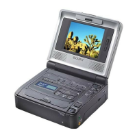
A
A: PSIG signal amplitude
V
6. Black Limit Adjustment (PD-133 board)
Set the common electrode drive signal level of LCD to the specified
value.
Mode Camera
Subject Arbitrary
Measurement Point Pin 4 of CN5502 (PSIG)
Measuring Instrument Oscilloscope
Adjustment Page D
Adjustment Address A6
Specified Value A=8.15 ± 0.08 Vp-p
7. Center Voltage Adjustment (PD-133 board)
Set the common electrode drive signal level of LCD to the specified
value.
Mode Camera
Subject Arbitrary
Measurement Point Pin 3 of CN5502 (VG)
Measuring Instrument Digital voltmeter
Adjustment Page D
Adjustment Address AB
Specified Value A=7.00 ± 0.03 Vp-p
Adjusting method:
Order Page Address Data Procedure
1 0 01 01
22 0E61
32 0F
Set the following data
5B (NTSC), 53 (PAL)
4D A6
Change the data and set the
voltage (A) to the specified value.
(The data should be “00” to “0F”)
5 D A6 Press PAUSE button.
62 0E00
72 0F00
8 0 01 00
Adjusting method:
Order Page Address Data Procedure
1 0 01 01
2D AB
Change the data and set the DC
voltage (A) to the specified value.
(The data should be “00” to “7F”)
3 D AB Press PAUSE button.
4 0 01 00
Fig. 5-3-31
Note: NTSC model: DCR-TRV320/TRV320P
PAL model: DCR-TRV320E