EasyManua.ls Logo

Sony HCD-HPX7 Service Manual

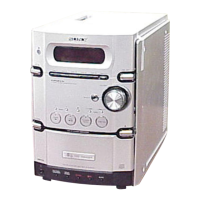
Sony HCD-HPX7
110 pages
To Next Page IconTo Next Page
Page #1 background imageLoading...
Page #1 background image
SERVICE MANUAL
Sony Corporation
Home Audio Company
Published by Sony Engineering Corporation
Canadian Model
AEP Model
UK Model
E Model
Australian Model
COMPACT DISC DECK RECEIVER
9-877-911-01
2004F1678-1
© 2004.06
Ver 1.0 2004.06
SPECIFICATIONS
HCD-HPX7
HCD-HPX7 is the amplifier, CD player,
tape deck and tuner section in CMT-HPX7.
SPEAKER: o Accepts impedance of 6 t
16 ohms.
CD player section
Laser Semiconductor laser
(λ=780 nm)
Emission duration:
continuous
Frequency response 20 Hz – 20 kHz
Tape deck section
Recording system 4-track 2-channel, stereo
Frequency response 50 – 13,000 Hz (±3 dB),
using Sony TYPE I
cassettes
Tuner section
FM stereo, FM/AM superheterodyne tuner
FM tuner section
Tuning range 87.5 – 108.0 MHz
Antenna FM lead antenna
Antenna terminals 75 ohms unbalanced
I
ntermediate frequency 10.7 MHz
AM tuner section
Tuning range
Pan-American model: 530 – 1,710 kHz
(with the tuning interval
set at 10 kHz)
531 – 1,710 kHz
(with the tuning interval
set at 9 kHz)
European model: 531 – 1,602 kHz
(with the tuning interval
set at 9 kHz)
Other models: 530 – 1,710 kHz
(with the tuning interval
set at 10 kHz)
531 – 1,602 kHz
(with the tuning interval
set at 9 kHz)
Antenna AM loop antenna, external
antenna terminal
Intermediate frequency 450 kHz
General
Power requirements
North American model: 120 V AC, 60 Hz
120 V AC, 60 Hz
220 V AC, 60 Hz
120 V AC, 50/600 Hz
Australian model: 230 – 240 V AC, 50/60 Hz
European model: 230 V AC, 50/60 Hz
Taiwan model:
Korean model:
Mexican model:
Other models: 120 V, 220 V or 230 – 240
V AC, 50/60 Hz
Adjustable with voltage
selector
Power consumption
European model: 115 W
Other models: 90 W
Design and specifications are subject to change
without notice.
Main unit
Amplifier section
European model:
DIN power output (rated): 50 + 50 W
Continuous RMS power output (reference):
60 + 60 W
(6 ohms at 1 kHz, DIN)
(6 ohms at 1 kHz, 10%
THD)
Music power output (reference): 100 + 100 W
Other models:
The following measured at AC 240 V, AC 220 V or AC
120 V
DIN power output (rated): 45 + 45 W
(6 ohms at 1 kHz, DIN)
Continuous RMS power output (reference):
50 + 50 W
Outputs
PHONES: Accepts headphones with
an impedance of 8 ohms or
more.
Inputs
MD/VIDEO: Sensitivity 450/250 mV,
impedance 47 kilohms
(6 ohms at 1 kHz, 10%
THD)
Model Name Using Similar Mechanism HCD-HPX9
CD CD Mechanism Type CDM82A-F1BD81
Section Base Unit Name BU-F1BD81A
Optical Pick-up Block Name KSM-215DCP
Tape deck Model Name Using Similar Mechanism HCD-HPX9
Section Tape Transport Mechanism Type CMAL5Z225A

Table of Contents

Question and Answer IconNeed help?

Do you have a question about the Sony HCD-HPX7 and is the answer not in the manual?

Sony HCD-HPX7 Specifications

General IconGeneral
BrandSony
ModelHCD-HPX7
CategoryReceiver
LanguageEnglish

Summary

SPECIFICATIONS

SERVICING NOTES

NOTES ON HANDLING THE OPTICAL PICK-UP BLOCK OR BASE UNIT

Precautions for handling sensitive optical components to prevent ESD damage.

NOTES ON LASER DIODE EMISSION CHECK

Safety guidelines for observing laser diode emission to avoid eye damage.

DISASSEMBLY

DISASSEMBLY FLOW-1

Outlines the initial sequence of steps for disassembling the main unit.

DISASSEMBLY FLOW-2

Continues the step-by-step disassembly process for various internal components.

OPTICAL PICK-UP BLOCK

Details the disassembly of the optical pick-up assembly.

CD MECHANISM DECK (CDM82A)

Covers the disassembly of the CD mechanism unit itself.

OPTICAL PICK-UP (KSM-215DCP)

Details the removal of the optical pick-up module.

ASSEMBLY

ASSEMBLY FLOW

Provides a sequential overview of the assembly process after disassembly.

TEST MODE

[COMMON TEST MODE]

Enters a diagnostic mode for testing various functions.

ELECTRICAL ADJUSTMENTS

REC BIAS ADJUSTMENT

Procedure for adjusting the recording bias level for optimal tape performance.

DIAGRAMS

BLOCK DIAGRAM — CD SERVO SECTION —

Illustrates the functional blocks and signal flow of the CD servo system.

BLOCK DIAGRAM — MAIN SECTION —

Shows the block diagram for the main processing and audio sections.

BLOCK DIAGRAM — PANEL/POWER SUPPLY SECTION —

Depicts the block diagram for the front panel controls and power supply.

SCHEMATIC DIAGRAM — CD BOARD —

Provides the detailed circuit diagram for the CD board.

SCHEMATIC DIAGRAM — MAIN BOARD (1/3) —

First part of the main board circuit diagram.

SCHEMATIC DIAGRAM — MAIN BOARD (2/3) —

Second part of the main board circuit diagram.

SCHEMATIC DIAGRAM — AMP BOARD —

Provides the circuit diagram for the amplifier board.

SCHEMATIC DIAGRAM — PANEL SECTION —

Provides circuit diagrams for panel and headphone boards.

SCHEMATIC DIAGRAM — POWER BOARD —

Provides the circuit diagram for the power board.

EXPLODED VIEWS

CD MECHANISM DECK SECTION-1 (CDM82A)

Exploded view of the CD mechanism, Part 1.

CD MECHANISM DECK SECTION-2 (CDM82A)

Exploded view of the CD mechanism, Part 2.

CD MECHANISM DECK SECTION-3 (CDM82A)

Exploded view of the CD mechanism, Part 3.

Related product manuals