HT-ST5000
17
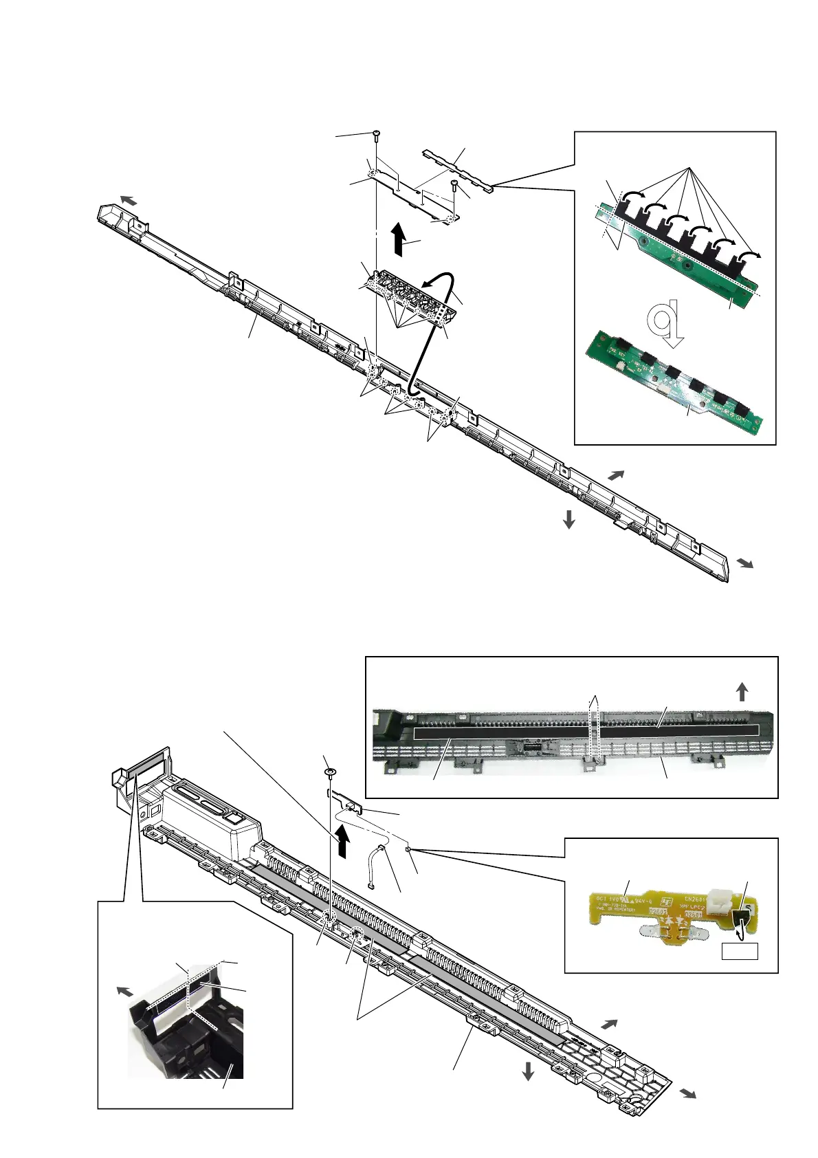
2-6. KEY BOARD, BUTTON
2-7. IR-REPEATER1 BOARD
4 KEY board
Note 1:
When installing the KEY board,
align the two bosses and two holes.
1 two screws
(BTP2.6 u 8)
2
Remove the KEY board
block in the direction of
the arrow.
hole
hole
boss
boss
KEY board
cushion
(button QG)
Bend.
3 cushion
(button QG)
1 two screws
(BTP2.6 u 8)
5
Remove the button
in the direction of
the arrow.
rear cover block
$IIL[LQJWKHFXVKLRQEXWWRQ4*
guide line
KEY board
rear side
top side
left side
right side
6
button
Note 2:
When installing the button,
align the seven bosses and
seven holes.
two bosses
two bosses
three bosses
hole
hole
five
holes
1 screw
(PWH3 u 8)
5 IR-REPEATER1 board
3 connector
(CN2601)
guide line
guide line (center)
saranet
cushion
(Reference)
3DVWLQJSRVLWLRQRI
WKHVDUDQHWFXVKLRQ
2
Draw the
IR-REPEATER1 board
block out of the two slots.
panel (back L) assy block
guide line
cushion (T05)
cushion (T05)
cushion (F)
IR-REPEATER1 board
rear side
bottom side
left side
right side
–,QQHUYLHZ–
two cushions (T05)
(See Fig. A)
panel (back L) assy block
)LJ$!
3DVWLQJSRVLWLRQRIWKHFXVKLRQ7
(Reference)
–,QQHUYLHZ–
bottom side
slot
slot
4
cushion (F)
3DVWLQJSRVLWLRQRIWKHFXVKLRQ)
Bend.
panel (back L) assy block
 Loading...