HT-ST5000
26
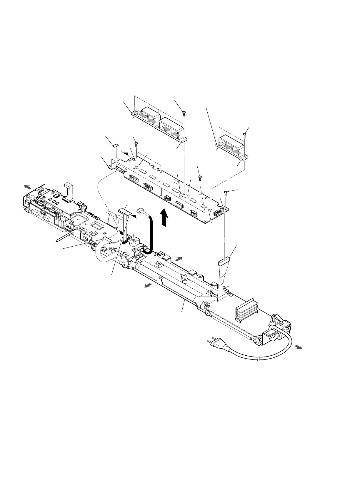
2-17. AMP BOARD
5 three screws
(transistor)
5 two screws
(transistor)
3 FFC 16P
(CN7007)
8 screw
(BVTP3 u 8)
8 four screws
(BVTP3 u 8)
8 two screws
(BVTP3 u 8)
4 radiation sheet
1 BAR POWER board
cable connector
(CN7001)
rib
rib
hole
hole
9 AMP board
Note 1:
When installing the AMP board,
align the two ribs and two holes.
7 heat sink (AMP-A)
Note 2:
When installing the heat sink (AMP-A),
spread the compound referring to
“SPREADING OF COMPOUND”
on page 8.
Note 3:
When installing the heat sink (AMP-A),
align the two bosses and two holes.
6 heat sink (AMP-B)
Note 2:
When installing the heat sink (AMP-B),
spread the compound referring to
“SPREADING OF COMPOUND”
on page 8.
Note 3:
When installing the heat sink (AMP-B),
align the two bosses and two holes.
2 MB-1611 board
cable connector
(CN7004)
terminal side
bottom side
top side
right side
left side
D
D
chassis block
hole
boss
boss
boss
boss
hole
hole
hole
 Loading...