HT-ST5000
20
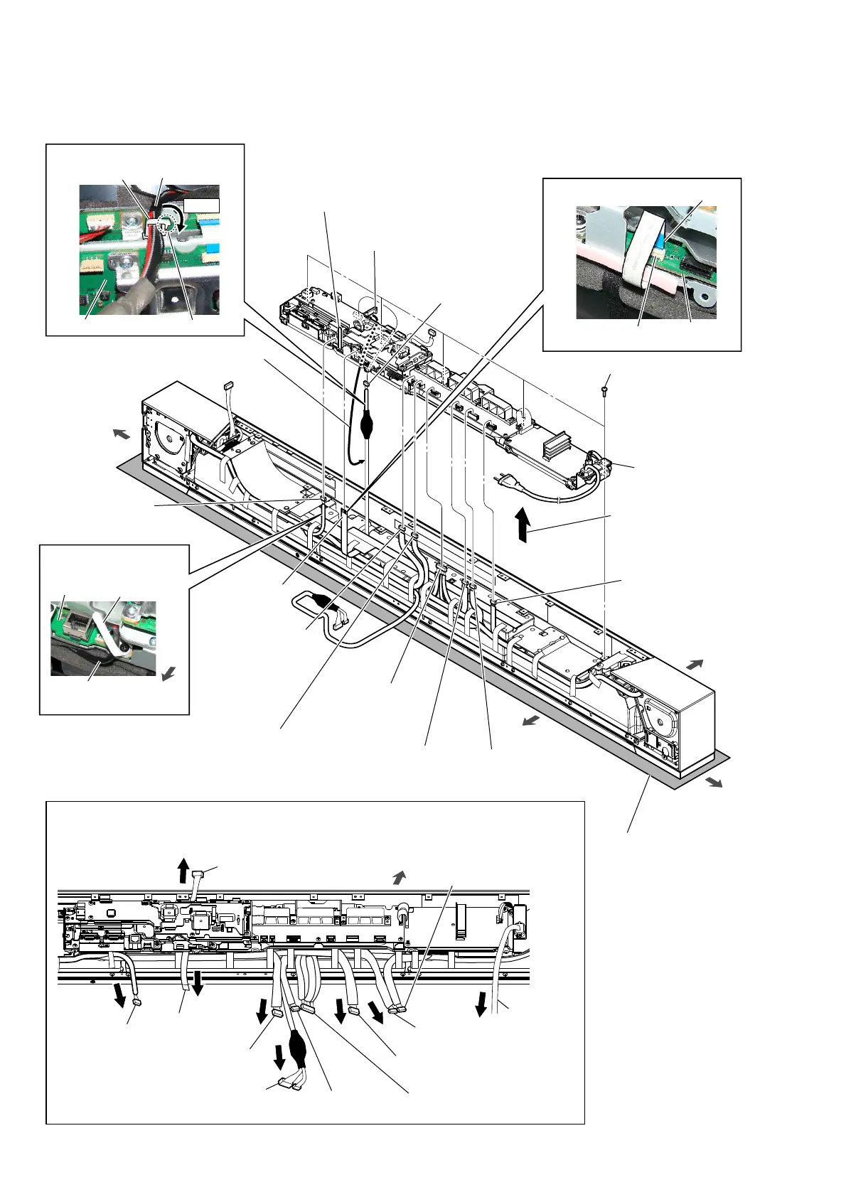
2-10. CHASSIS BLOCK-2
bottom side
Note 1:
Lay a soft piece of cloth
under the unit to avoid
damaging the grille assy.
right side
left side
0 five screws
(BVTP3 u 8)
qg
chassis block
(See Fig. E)
1 front L-ch speaker
connection cable
connector (CN7002)
8 Remove the wire from
the wire holder.
9 CHUKEI-WIRE
board cable
connector (CN501)
2 front R-ch speaker
connection cable
connector (CN7003)
3 center speaker
connection cable
connector (CN7005)
4 center speaker
connection cable
connector
(CN6002)
top side
6 top R-ch speaker
connection cable
connector (CN6005)
5 top L-ch speaker
connection cable
connector (CN6003)
7 FFC 16P
(CN3007)
wire holder
CHUKEI-WIRE
board cable
MB-1611
board
MB-1611
board
qd Draw the WLAN/BT combo card
cable out of the mini clamper.
:LUHVHWWLQJ
:LUHVHWWLQJ
qa
Lift up the chassis
block in the direction
of the arrow.
WLAN/BT combo
card cable
mini clamper
DSP board
Note 2:
Draw out the nine cables, FFC and power cord before installation.
bottom
side
qs Unlock the
mini clamper.
qf WLAN/BT combo
card cable connector
(CN503)
1RWHDERXWLQVWDOOLQJWKHFKDVVLVEORFN
Lock.
claw
:LUHVHWWLQJ
CN3007
)LJ(!
terminal side
top side
CHUKEI-WIRE
board cable
top L-ch speaker
connection cable
CHUKEI-WIRE
board cable
front L-ch speaker
connection cable
power cord
front R-ch speaker
connection cable
top R-ch speaker
connection cable
center speaker
connection cable
FFC 16P
WLAN/BT combo card cable
center speaker
connection cable
 Loading...