HT-ST5000
22
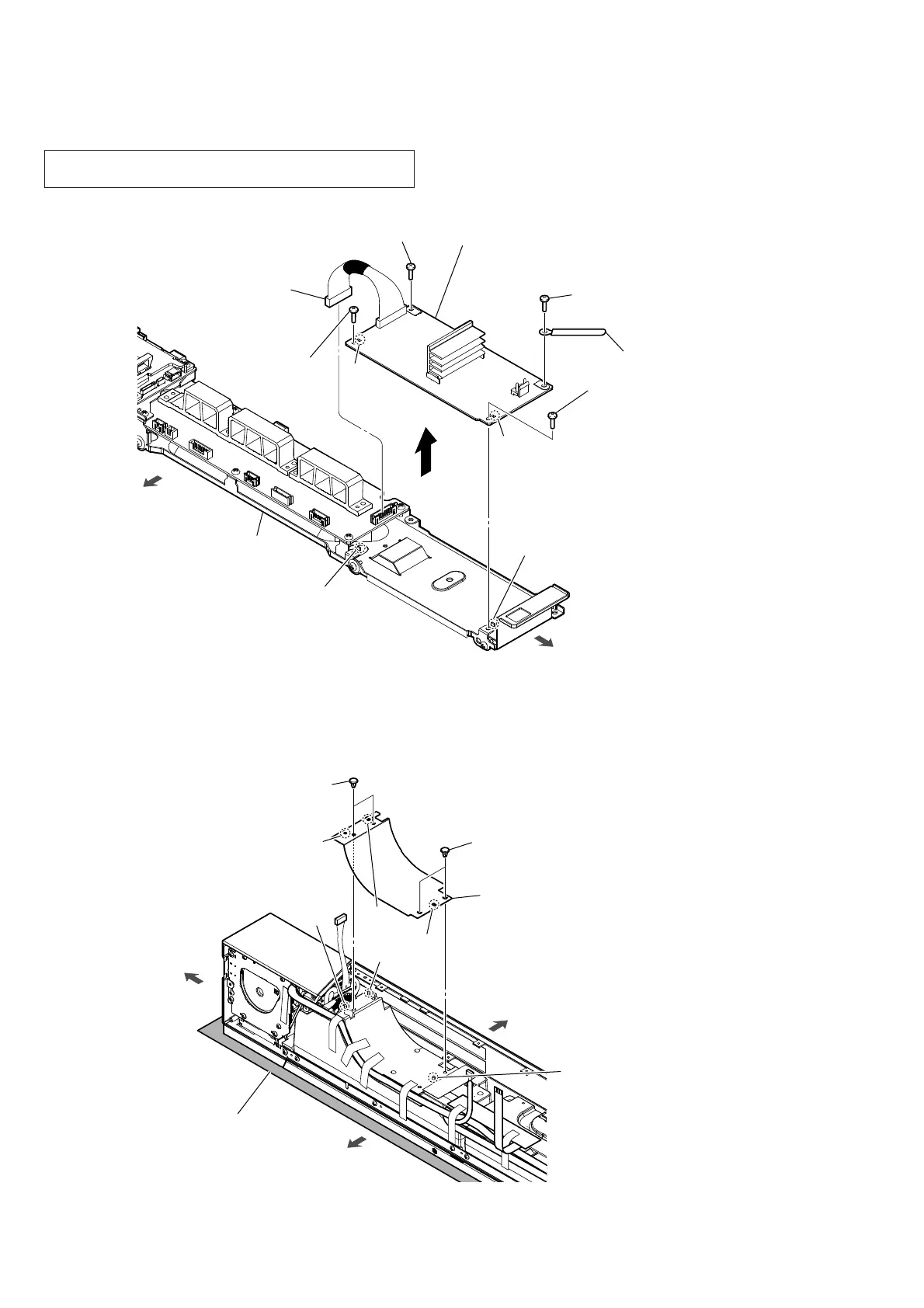
2-12. BAR POWER BOARD
2-13. SHEET (R)
bottom side
left side
2 screw
(BV3 u 8 CU)
3 screw
(BVTP3 u 8)
3 screw
(BVTP3 u 8)
4 wiring stopper
5 BAR POWER board
Note 2:
When installing the BAR POWER board,
align the two ribs and two holes.
rib
rib
hole
hole
1 BAR POWER board
cable connector
(CN7001)
3 screw
(BVTP3 u 8)
chassis block
1 two canoe clips
(small)
1 two canoe clips
(small)
2 sheet (R)
Note 1:
The sheet (R) is affixed using adhesive sheet.
Note 2:
When installing the sheet (R), align the three
bosses and three holes.
hole
hole
boss
bottom side
right side
top side
Note 3:
Lay a soft piece of cloth
under the unit to avoid
damaging the grille assy.
hole
boss
boss
Note 1: When the BAR POWER board is replaced, refer to “BOND
FIXED POSITION OF ELECTRICAL PARTS” on page 9.
 Loading...