HT-ST5000
HT-ST5000
7171
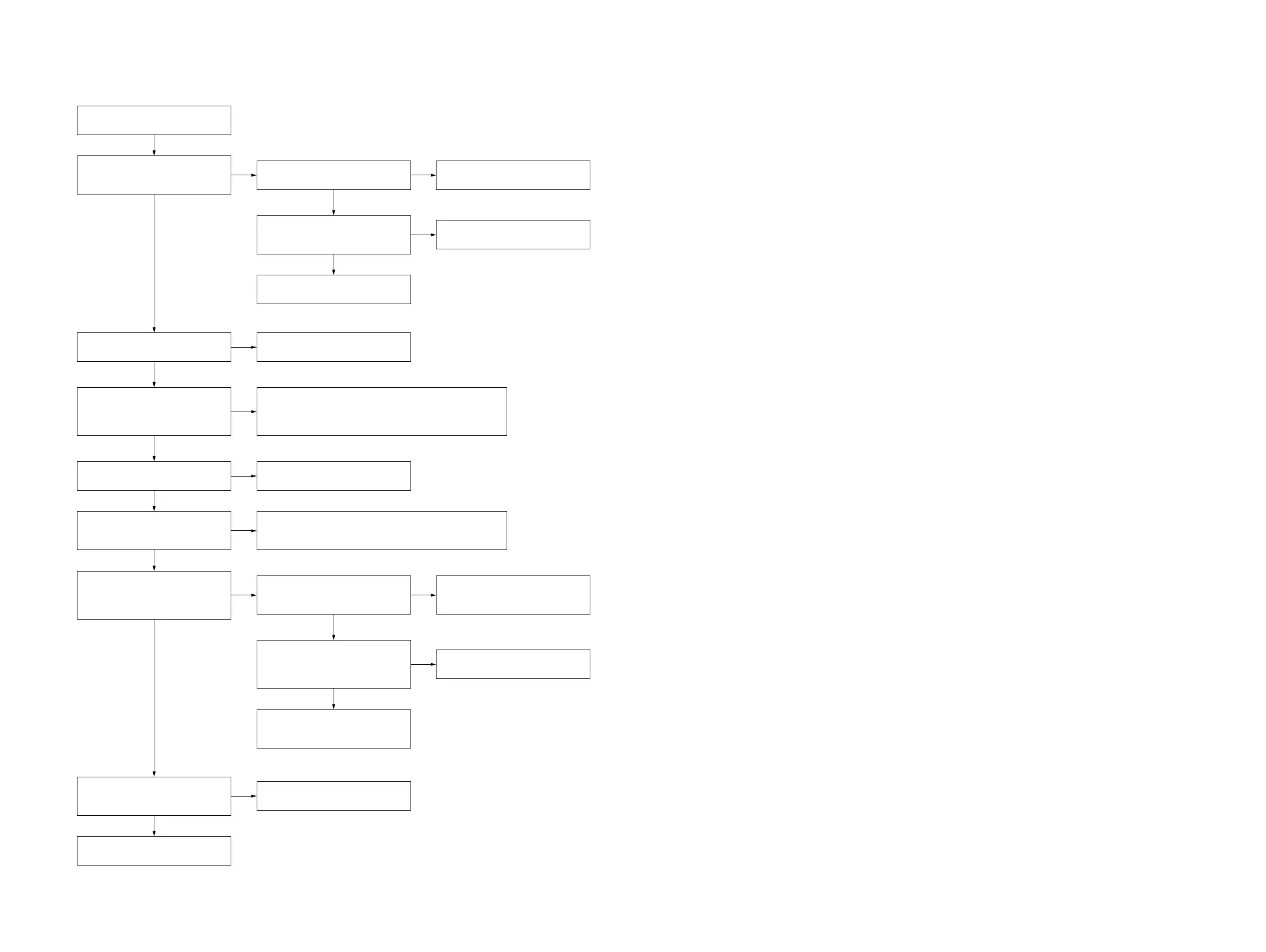
4. Power is not turned on
Power is not turned on.
(OLED display does not appear)
Yes
Yes
The voltage of the following is 28 V.
BAR POWER board:
CN902 pin 3 to 5
No
Fuse (F901) on the BAR POWER
board conduct the electricity.
No
Replace the fuse (F901) on the
BAR POWER board.
Fusible resistor (R923) on the BAR
POWER board conduct the
electricity.
Replace the BAR POWER board.
Replace the MB-1611 board.
No
Replace the fusible resistor (R923)
on the BAR POWER board.
Yes
Yes
Fuse (F7009) on the AMP board
conduct the electricity.
No
Replace the fuse (F7009) on the
AMP board.
No
The voltage of the following is 3.3 V.
MB-1611 board:
B+ line side of capacitor (C357)
(IC306 pin 1)
Yes
Yes
Check the area surrounding IC306 on the MB-1611 board,
and check the connection between the MB-1611 board
(CN301) and the AMP board (CN7004).
If there is no abnormality, replace the MB-1611 board.
Vibrator (X3000) on the MB-1611
board is oscillated after AC input.
The reset signal is inputted to pin
57 of IC3002 on the MB-1611 board
after AC input.
No
Yes
No
Check the area surrounding IC3002, IC3198 and transistor
(Q3010) on the MB-1611 board.
If there is no abnormality, replace the MB-1611 board.
The voltage of the following is 12 V.
MB-1611 board: CN3007 pin 2
The voltage of the following is 3.3 V.
MB-1611 board: CN3007 pin 3
Yes
The flexible flat cable (FFC7)
connecting the MB-1611 board and
DISPLAY board is damaged.
Yes
Replace the DISPLAY board and
the OLED display.
No
Replace the flexible flat cable
(FFC7).
Yes
Fuse (F7001) on the AMP board
and resistor (R321) on the MB-1611
board conduct the electricity.
No No
Replace the fuse (F7001) on the
AMP board.
Replace the MB-1611 board.
The PCONT signal of the following
is outputted.
MB-1611 board:
IC3002 pin 71 (PCONT_OLED)
Yes
Replace the MB-1611 board.
No
Check and repair the area
surrounding transistor (Q301, Q302)
on the MB-1611 board.
Yes
 Loading...