5-23
16.White Balance Check (FD83)
Mode STILL
Subject Clear chart
(Color reproduction adjustment
frame)
Filter Filter C14 for color temperature
correction
ND filter 1.0, 0.4 and 0.1
Measurement Point Video terminal of A/V OUT jack
(75 terminated)
Measuring Instrument Vectorscope
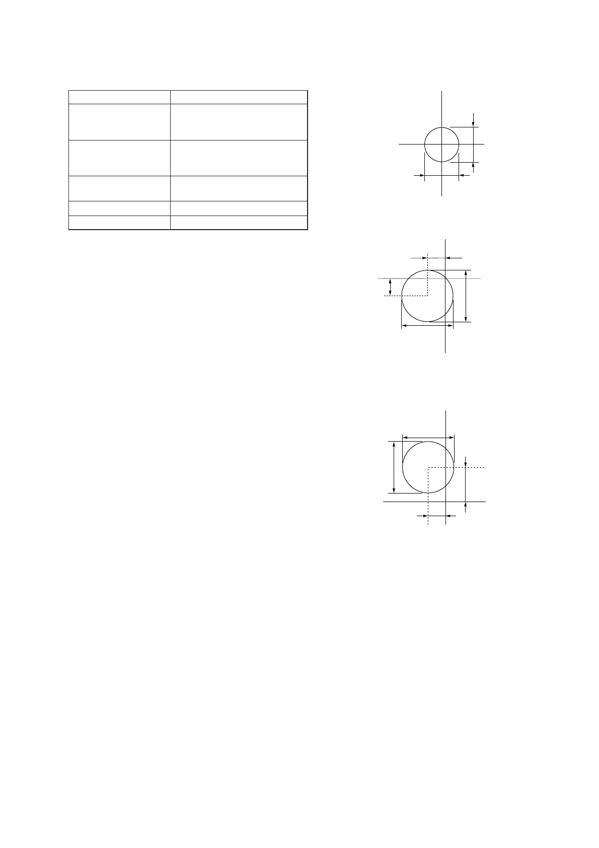
Specified Value Fig. 5-1-20 (A) to (C)
Checking method:
1) Check that the lens is not covered with either filter.
2) Select page: 6, address: 10, and set data: 58.
3) Select page: B, address: 41, set data: 30, and press the PAUSE
button of the adjusting remote commander.
4) Select page: 6, address: 01, set data: 0F, and press the PAUSE
button of the adjusting remote commander.
5) Check that the center of the white luminance point is within
the circle shown Fig. 5-1-20 (A).
6) Select page: 6, address: 01, set data: 23, and press the PAUSE
button of the adjusting remote commander.
7) Place the C14 filter on the lens.
8) Check that the center of the white luminance point settles in
the circle shown Fig. 5-1-20 (B).
9) Remove the C14 filter, and place the ND filter 1.5 (1.0 + 0.4 +
0.1) on the lens.
10) Check that the white luminance point stopped moving, and
then remove the ND filter 1.5.
11) Check that the center of the white luminance point settles within
the circle shown Fig. 5-1-20 (C).
Processing after Completing Adjustments:
1) Select page: 6, address: 10, and set data: 00.
2) Select page: B, address: 41, set data: 00, and press the PAUSE
button of the adjusting remote commander.
3) Select page: 6, address: 01, set data: 00, and press the PAUSE
button of the adjusting remote commander.
Fig. 5-1-20 (A)
Fig. 5-1-20 (B)
Fig. 5-1-20 (C)
R-Y
B-Y
3mm
3mm
2.0mm
1.0mm