5-27
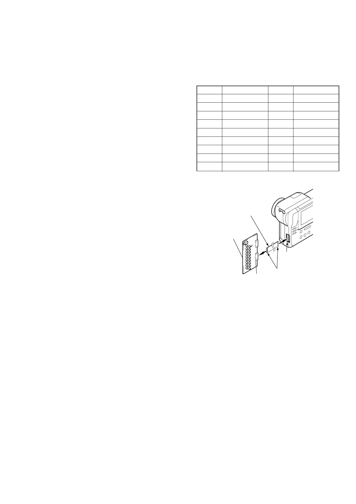
Fig. 5-1-21
Note: Don't use the 12 pin flexible board of
CPC-9 jig. It causes damage to the unit.
1-5. LCD SYSTEM ADJUSTMENTS
Before perform the camera system adjustments, check that the
specified values of “VIDEO SYSTEM ADJUSTMENTS” are sat-
isfied.
Note 1: The back light (fluorescent tube) is driven with high volt-
age AC power. Therefore, do not touch the back light
directly, otherwise you will feel an electric shock.
Note 2: Taken an extreme care not to destroy the liquid crystal
display module by static electricity when replacing it.
Note 3: Adjust the brightness to the center with the BRIGHT +/-
buttons.
[Adjusting connector]
Most of the measuring points for adjusting the LCD system are
concentrated in CN801 of the PK-47/48 board.
Connect the Measuring Instruments via the CPC-9 jig (J-6082-
393-B).
The following table shows the Pin No. and signal name of CN801.
Pin No. Signal Name Pin No. Signal Name
1 MC PA05 10 UNREG
2 C OUT 11 LANC IN
3 Y OUT 12 LANC OUT
4 REG GND 13 XPOWER SW
5 N.C. 14 MAKER RECOG
6 SYS V 15 INDEX
7 HSY 16 TRACK 00
8 COM 17 FDD RFB
9 VG 18 FDD RFA
Table 5-1-7
CPC-9 jig
(J-6082-393-B)
CN2
Conductor side
PK-47/48 board
CN801
18 pin flexible board
(Note)