5-31
7. Color Adjustment (PK-47/48 Board)
Set the color saturation to the standard value.
If, deviated, the color will be dark or light.
Mode PLAY
Signal Color bar (Test signal)
Measurement Point Pin (9) of CN801 (VG)
Measuring Instrument Oscilloscope
Adjustment Page D
Adjustment Address 81
Specified Value A = 490 ± 50 mVp-p (FD83)
A = 540 ± 50 mVp-p (FD88)
Adjusting method:
1) Select page: 0, address: 01, and set data: 01.
2) Select page: 2, address: 06, and set data: 01.
3) Select page: 5, address: F1, and set data: 04.
4) Select page: D, address: 81, change the data and set the volt-
age (A) between the white and green to the specified value.
5) Press the PAUSE button of the adjusting remote commander.
Processing after Completing Adjustments:
1) Select page: 5, address: F1, and set data: 00.
2) Select page: 2, address: 06, and set data: 00.
3) Select page: 0, address: 01, and set data: 00.
8. V-COM Level Adjustment (PK-47/48 Board)
Set the common electrode drive signal level of LCD to the speci-
fied value.
Mode PLAY
Signal Stair-step signal of 10 steps (non
burst)
(Test signal)
Measurement Point Pin (8) of CN801 (COM)
Measuring Instrument Oscilloscope
Adjustment Page D
Adjustment Address 86
Specified Value A = 6.10 ± 0.05 Vp-p (FD83)
A = 6.50 ± 0.05 Vp-p (FD88)
Adjusting method:
1) Select page: 0, address: 01, and set data: 01.
2) Select page: 2, address: 06, and set data: 01.
3) Select page: 5, address: F1, and set data: 03.
4) Select page: D, address: 86, change the data and set the V-
COM signal level (A) to the specified value.
5) Press the PAUSE button of the adjusting remote commander.
Processing after Completing Adjustments:
1) Select page: 5, address: F1, and set data: 00.
2) Select page: 2, address: 06, and set data: 00.
3) Select page: 0, address: 01, and set data: 00.
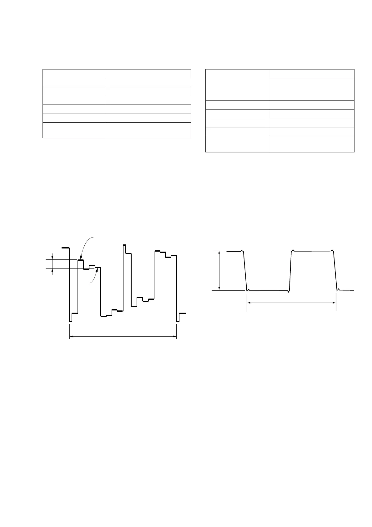
Fig. 5-1-25
Fig. 5-1-26
A
Green
White
2H
A
2H