5-30
5. Bright Adjustment (PK-47/48 Board)
Set the level of the VIDEO signal for driving the LCD to the speci-
fied value.
If deviated, the LCD screen image will be blackish or saturated
(whitish).
Mode PLAY
Signal Stair-step signal of 10 steps (non
burst)
(Test signal)
Measurement Point Pin (9) of CN801 (VG)
Measuring Instrument Oscilloscope
Adjustment Page D
Adjustment Address 80
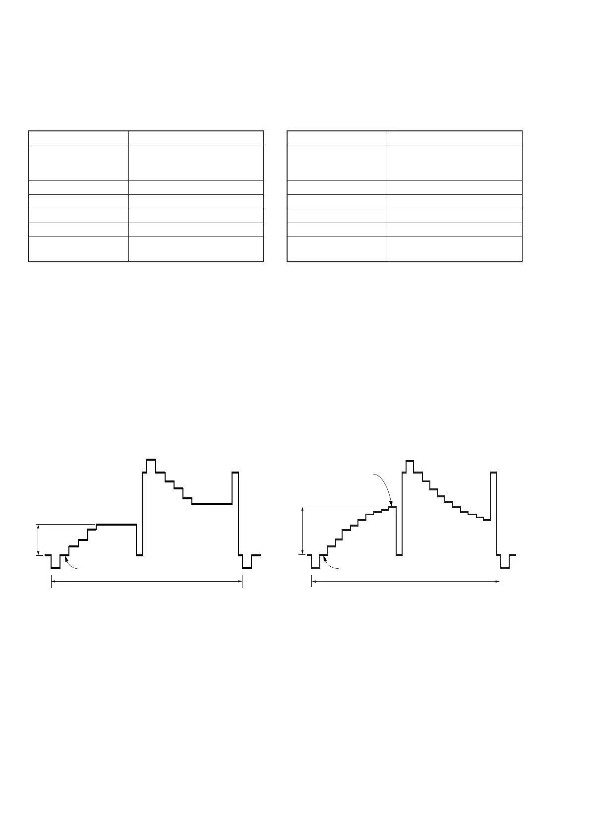
Specified Value A = 1.80 ± 0.05 Vp-p (FD83)
A = 1.81 ± 0.05 Vp-p (FD88)
Adjusting method:
1) Select page: 0, address: 01, and set data: 01.
2) Select page: 2, address: 06, and set data: 01.
3) Select page: 2, address: 10, and set data: 01.
4) Select page: 5, address: F1, and set data: 03.
5) Select page: D, address: 80, change the data and set the volt-
age (A) between the pedestal and white level to the specified
value.
6) Press the PAUSE button of the adjusting remote commander.
Processing after Completing Adjustments:
1) Select page: 5, address: F1, and set data: 00.
2) Select page: 2, address: 10, and set data: 00.
3) Select page: 2, address: 06, and set data: 00.
4) Select page: 0, address: 01, and set data: 00.
6. Contrast Adjustment (PK-47/48 Board)
Set the level of the VIDEO signal for driving the LCD to the speci-
fied value.
If deviated, the LCD screen image will be blackish or saturated
(whitish).
Mode PLAY
Signal Stair-step signal of 10 steps (non
burst)
(Test signal)
Measurement Point Pin (9) of CN801 (VG)
Measuring Instrument Oscilloscope
Adjustment Page D
Adjustment Address 84
Specified Value A = 2.90 ± 0.07 Vp-p (FD83)
A = 3.17 ± 0.07 Vp-p (FD88)
Adjusting method:
1) Select page: 0, address: 01, and set data: 01.
2) Select page: 2, address: 06, and set data: 01.
3) Select page: 5, address: F1, and set data: 03.
4) Select page: D, address: 84, change the data and set the volt-
age (A) between the 0 IRE (pedestal) and 100 IRE to the speci-
fied value.
5) Press the PAUSE button of the adjusting remote commander.
Processing after Completing Adjustments:
1) Select page: 5, address: F1, and set data: 00.
2) Select page: 2, address: 06, and set data: 00.
3) Select page: 0, address: 01, and set data: 00.
Fig. 5-1-23
0 IRE
A
2H
100 IRE
0 IRE
A
2H
Fig. 5-1-24